Author Nahuel Riva
Category Hardware
Tags Philips, TriMedia, ipcam, hardware, reverse-engineering, 2020
Third part of a blog post series about our approach to reverse engineer a Philips TriMedia based IP camera.
Introduction
Welcome to the final chapter of the Trimedia series.
In the first part of the series, I introduced this research project, showing the different steps I took in order to analyze the firmware and the hardware of the camera. Then, in the second part, I presented the Philips TriMedia architecture, its instruction set and assembly. This time, I'll show you, through a practical example, how a Philips TriMedia instruction can be disassembled.
Don't be scared, I'm sure that understanding all the points and the process of disassembling an instruction will eventually require more than one read, but if you are really interested in the subject I'm sure you'll manage to get all the concepts.
In my case, understanding everything took me many hours of reading the docs, looking at the disassembler code and do my own experiments, and even more hours of work to try to explain all this mess in the blog post series. Thus it may require some effort from the reader in order to get the basic idea of how all the disassembling process works.
It's a very long read so I advise you to get your favorite drink and eat something while reading.
Going to the darkness
Now, it's time to explain how all this works in real life with a real life example :)
Let us take a small binary named 'tinytest.o' that comes with the tm32disassembler in the test folder in order to explain how we can disassemble a TriMedia (TM for short) instruction. At the beginning, it can be a little bit tricky but after playing around for some time, it starts to make sense. I've chosen this binary because it is really small (6 instructions) and it is a good explanation support.
The following are the hexadecimal bytes of the binary:
7C 47 81 43 60 21 60 A0 85 50 80 30 03 C1 08 00 40 E0 60 45 60 11 40 0F 80 00 57 01 D5 43 21 51 88 08 83 68 C1 D7 21 21 83 68 01 81 28 06 04 22 C1 95 C1 FC A7 A2 11 A2 22 01 22 07 00 A0 95 95 FE FF 02 07 E0 A1 FC 43 07 00 A2 7E 01 AA 82 08 11 02
One thing I mentioned during my talks at Ekoparty 2018 and Troopers 2019 is that the process of disassembling a TM instruction involves different steps that can be summarized as follows:
get the instruction length;
get the operation size (compressed size);
unpack the operation;
decode the operation.
How do we start disassembling these bytes? As I mentioned in the previous posts, the execution flow is divided into Decision Trees (dtree) and that's the first thing a TriMedia CPU does when processing an instruction, it creates a dtree. A dtree is always encoded with the 0xAA02 word and these bytes are used as the first format bit field in order to disassemble an instruction.
Before starting, I want to refresh some basic concepts that I will use during this post. Please, keep them in mind because I'm going to use them constantly, especially the format bits.
These are the basic concepts you have to keep in mind when reading the post:
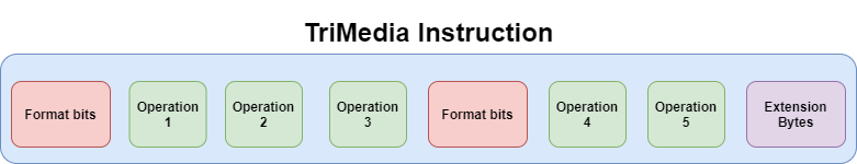
ONE INSTRUCTION is composed of up to FIVE OPERATIONS;
an instruction has a minimum of three operations;
the NOP operation has no length;
there is, at least, ONE group of format bits at the beginning of an instruction;
format bits are used to describe properties of the operations inside an instruction;
format bits are, at most, 10 bits. Five groups of two bits each. Three groups are the minimum that can be found in an instruction. Five is the maximum;
there are extension bits that can be used to extend an instruction from three operations up to five operations;
a function in the TriMedia ASM starts with a dtree.
The following diagram demonstrates, in a general manner, how a TriMedia instruction is composed:
Step 1 - Get the length of the instruction
The first step is the easiest one. We want to know how long is our instruction and, in order to do that we have to know how many operations are inside it. But not only how many operations but also how many format bits and extension bytes. All this information is provided by the format bits themselves.
In the second part of the series we saw there is a table that gives us information about all the possible combinations format bits may have:
| Format (2i) (lsb) | Format (2i+1) (msb) | Meaning |
|---|---|---|
| 0 | 0 | Issue slot i is used and an operation for it is available in the instruction. The operation size is 26 bits. The size of the extension is 0 bytes. |
| 1 | 0 | Issue slot i is used and an operation for it is available in the instruction. The operation size is 34 bits. The size of the extension is 1 byte. |
| 0 | 1 | Issue slot i is used and an operation for it is available in the instruction. The operation size is 42 bits. The size of the extension is 2 bytes. |
| 1 | 1 | Issue slot is unused and no operation for it is included in the instruction. |
By reading this table, we get exactly the amount of bits required for each operation and the extension bytes. We already know that the format bits are located at the beginning of the instruction thus we have to get them and process them.
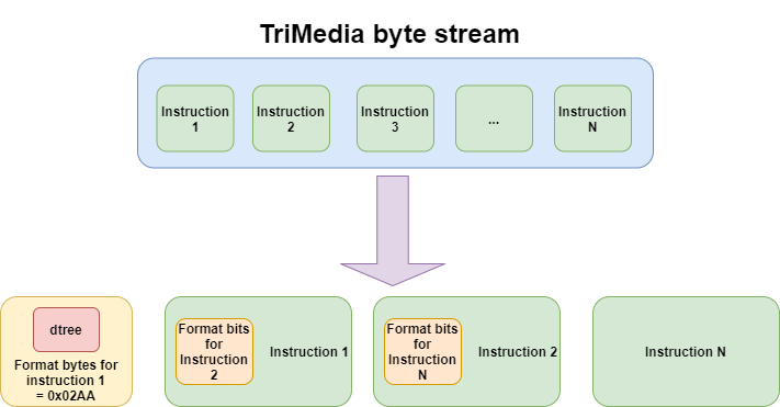
As I already mentioned, the execution flow in the TriMedia ASM is indicated by a dtree and the bytes representing the dtree are used also as the only uncompressed instruction (branch):
Format bytes: 0x02AA -> binary form: 0000 0010 1010 1010
Issue slot no: 0
Every time you start disassembling a TriMedia stream, you have to remember the dtree bytes because you must start by processing them. They are implicitly taken as the first group of format bits for the first instruction. Then, the format bits at the beginning of the first instruction are used as format bits for the next instruction. Let's try to explain it better with a picture:
At this point, we already have 16 bits due to the first format field, but not all the bits are used, just 10 bits. Let's keep that in mind for the final calculation.
The astute reader will surely have noticed that, as the dtree always starts with 0x02AA, then the first instruction is always 224 bits long. Why? because the format bits are {01, 01, 01, 01, 01}, let's show them again:
Format bytes: 0x02AA -> binary form: 00 00 00 10 10 10 10 10 (read it from right to left, we are working with little endianess, we have to swap the bytes)
                                              ^^ ^^ ^^ ^^ ^^
If we pay attention to the previous table, we can infer that the combination of 0 (lsb) and 1 (msb) means:
Issue slot i is used and an operation for it is available in the instruction.
The operation size is 42 bits.
The size of the extension is 2 bytes.
At the moment, we know that the instruction contains 5 operations with 42 bits each.
One remark: the specs says that if the instruction contains more than three operations, we have to add 8 bits for the format field of the second group of operations (2 operations). By doing some calculation, we infer that the 224 bits are formed by the first 16 bits, 5 operations with 40 bits each (the 2 bits left in each operation, which are the formats bits, are included in the first 16 bits) and the final 8 bits for the second format field as a consequence of the additional 2 operations.
To get a clearer idea of what I'm talking about, look at the following code extracted from the disassembler:
uint16_t instructionlength(uint16_t formatbits) {
        uint32_t i;
        uint16_t len = 0, instrcount = 0;

        len = 16;           // add the two bytes for the 1st format field
        for(i=0;i<5;i++)
        switch(formatbits >> (2 * i) & 3) {
                case 0  :   len += 24;  // 26-bit operation
                                        instrcount++;
                                        break;
                case 1  :   len += 32;  // 34-bit
                                        instrcount++;
                                        break;
                case 2  :   len += 40;  // 42-bit operation
                                        instrcount++;
                                        break;
                case 3  :   break;      // 0-bit operation (NOP)
                default   : fprintf(stderr, "encoding error  (* -1 bits *)\n");
                                        return -1;
                }
        if(instrcount >3)
                len += 8;       // add eight bits for the format field of the 2nd group
        return len;
}
Please, note that until now, we didn't bother to talk about the bytes in the binary and we don't actually need the instruction length to strictly disassemble the instruction. However, we need it to calculate the amount of bytes we have to get from the binary.
Step 2 - Get the operation size
Getting the size of each operation is really simple. If you put attention to the previous step, you'd have noted that we have fixed sizes for operations (26, 34 and 42 bit operations). This information is provided, again, by the format bits, so the only thing we need to do is to read the bit fields corresponding to the current operation. Simple as that.
From Step 1, we know that all the operations inside the instruction are 42 bits long thus we'll have 2 extension bytes. We need to get the offset of those extension bytes and the bytes representing the operation itself with the parameters. This is what we are going to see in the next step.
What happens when processing the beginning of our byte stream?
As our first instruction has a 224 bits length (28 bytes), our bytes are the following:
7C 47 81 43 60 21 60 A0 85 50 80 30 03 C1 08 00 40 E0 60 45 60 11 40 0F 80 00 57 01
Remember that the first bytes are used as format bits for the next instruction and not for the one we are processing.
It means that 0x7C47 are the two bytes we have to analyze in order to known how long the next instruction is. In this case, by doing the previous analysis, we can conclude that the next instruction is 72 bits long:
format bytes 0x7C47 -> swap_bytes(0x7C47) -> 0x477C -> binary form -> 01 00 01 11 01 11 11 00
^^ ^^ ^^ ^^ ^^
Read it from right to left, the result is:
00: operation size is 26 bits;
11: no operation, size = 0 bits;
11: no operation, size = 0 bits;
10: operation size is 34 bits;
11: no operation, size = 0 bits.
The result is calculated as follows: 16 bits (format bytes) + 24 bits (1st op size - 2 bits) + 32 bits (2nd op size - 2 bits) = 72 bits = 9 bytes
A note about extension bytes when calculating the size of an operation
One last thing, in the second part of the series, I mentioned that extension bytes can be added to the operation in order to extend it. The number of bytes can be 0, 1 or 2, depending on the format bits. In the case of 26 bits operations, we have a 24-bits part plus 2 format bits. In the case of 34 bits operations, we have a 24-bits part, plus 2 format bits and 1 byte extension. In the case of 42 bits operations we have a 24-bits part, plus 2 format bits and 2 byte extensions. This is important when calculating the offset of the real operation inside the stream of the current instruction.
The following picture tries to show you how each operation is decomposed:
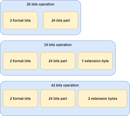
In the picture, format bits are shown next to the operation and extension bytes but this is not always the case. Don't think you are going to find it like that, in fact, you have to calculate those offsets to get the bytes from the stream.
If you are curious, you can take a look at the operationsize function in the tm32disassembler.
Step 3 - Unpack the operation
So far we have the following information:
the instruction length;
the size of each operation inside the instruction.
To continue disassembling the instruction, we need to know the offset of each operation inside the bit stream and, when relevant, the offset of the extension bytes.
For a better explanation, I'll use part of the code of tm32disassembler to show you how both offsets are calculated.
Get the offset of an operation
The operation offset is the one that will tell us where each operation is located in the bit stream. Please, take a look at the following code:
uint16_t operationoffset(uint16_t formatbits, uint8_t slotnumber) {
        uint16_t i, offset = 0, oplen = 0, opcount = 0;

        if (operationsize(formatbits, slotnumber) == 0) // a NOP in slotnumber, so operation size for that is zero
                return 0;

        for(i=0;i<slotnumber;i++) {
                oplen = operationsize(formatbits, i);
                if(oplen>0) {
                        opcount++;
                        offset+=24;
                }
        }
        if(opcount > 2)
                offset+=8;          // add the formatbits byte for the 2nd operations group, if used

        return offset;
}
As you can see, we only need the format bits and the slot number of the operation in order to calculate the offset. If our instruction contains a NOP, the offset for that operation in slot number i is 0.
It's important to note that the offset is calculated from the beginning of the instruction. Then, we need to count how many operations are inside our instruction till the slot number of the current operation and go adding up to 24 bits. Why 24 bits? That's the smallest operation size we can have (format bits are not taken into account). In other cases, we have extension bytes and our instruction is either 34 or 42 bits. Last but not least, we have to take into account if the operation is part of the second group of operations, and in that case, we need to add 8 more bits.
Now, let's go back to our instruction bytes:
7C 47 81 43 60 21 60 A0 85 50 80 30 03 C1 08 00 40 E0 60 45 60 11 40 0F 80 00 57 01
If we follow the above algorithm to calculate the offset for the first operation, we get the following result:
We know that the format bits for the instruction are 0x02AA, the slot number for the first operation is 0 and its format bits are 01. This means that offset is 0, basically, because the condition i < slotnumber is not satisfied, i and slotnumber are both 0. The second operation offset will be 24, the third one will be 48, the fourth one will be ... 80 and the fifth will be ... 104. Were you expecting 96 for the fourth and 192 for the fifth? :P No, both operations belong to the second group of operations so we need to add 8 bits.
As our first operation is 40 bits long, and knowing that we have 16 bits at the beginning of the stream for the format bytes, we know that our bit stream is going to be, at most, as long as:
7c 47       - 81 43 60 21 60
^^ ^^         ^^ ^^ ^^ ^^ ^^
(fb n ins)  -   (op bytes)
(fb n ins): format bytes for the next instruction;
(op bytes): bytes for the first operation.
We have what are supposed to be the bytes corresponding to our first operation but we need to remember that a 42 bit operation is composed of a 24 bits part, plus 2 bits for the format bits and a 2 bytes extension. It means these 5 bytes don't belong ONLY to our first operation. We'll see that the bytes of an operation, in this case with 42 bits, are scattered throughout the whole byte stream and, in fact, those five bytes contain part of the second operation. Anyway, we need to know where our extension bytes are in order to get the final bytes for our first operation.
Get the offset of the extension bytes
As in the previous step, I'm going to show you the code of how the extension bytes offset is calculated and then I'll finish by getting the bytes for the first operation in our first instruction.
The code to get the extension bytes of an operation is the following:
219 uint16_t extensionoffset(uint16_t formatbits, uint8_t slotnumber) {
220    uint32_t i;
221    uint16_t extbegin = 0, extoffset = 0,oplen = 0, opcount = 0;
222
223    if(operationsize(formatbits,slotnumber) <= 24)      // operation has no extension
224        return 0;
225
226    for(i=0;i<MAXSLOT;i++) { // count the number of non-NOP operations in the instruction.
227        oplen = operationsize(formatbits, i); // (count * 24) + format bytes is a pointer to the extension bytes
228        if(oplen>0)
229            opcount++;
230    }
231    extbegin+=(opcount*24);
232
233    if(opcount >3) //
234        extbegin+=8; // add format byte to ext. offset for 2nd operations group, if used
235
236    extoffset = extbegin;
237
238    for(i=0;i<slotnumber;i++) {
239        oplen = operationsize(formatbits, i);
240        if(oplen>0)
241            extoffset+= oplen - 24;
242    }
243    return extoffset;
244 }
As you can see, the beginning of the code is very similar to the one in the operationoffset function. The first thing it does is to check if the operation is a NOP, if that is the case, it doesn't have extension bytes.
If you remember the graph I used in the second part of the series about TriMedia to explain the instruction format with 4 and 5 operations, you see that extension bytes are located at the end of the instruction. In order to get them, the algorithm starts by counting how many operations there are inside the instruction at line #226 and then calculates the start offset of the extension bytes at line #231. Again, if we have more than 3 operations in an instruction, we must add 8 bits for the format bits of the second group, this is done at line #233. From line #238 onwards, it calculates the right offset for the extension byte of the current instruction, taking extbegin as the start.
In our case, opcount is 5 so extbegin is 120 (24*5) at line #231, then we have to add 8 because we have more than 3 operations thus extoffset will end up being 128. The comparison at line #238 is not satified (false) becase slotnumber is 0. At this point, we can also calculate the value for the next 4 operations:
operation 1: extoffset is 128;
operation 2: extoffset is 144;
operation 3: extoffset is 160;
operation 4: extoffset is 176;
operation 5: extoffset is 192.
extoffset is the bit offset from the start of the instruction. If we want to know which byte this bit offset corresponds to, we have to skip the first 16 bits of the format bytes and divide it by 8 (because each byte is composed of 8 bits). The values of extoffset for the five operations in our first instruction (in bytes) are the following. Note that as we have only 42 bits operations, we have 2 extension bytes:
operation 1: bit offset 128 --> byte offset 18;
operation 2: bit offset 144 --> byte offset 20;
operation 3: bit offset 160 --> byte offset 22;
operation 4: bit offset 176 --> byte offset 24;
operation 5: bit offset 192 --> byte offset 26.
Knowing that, it means that the bytes corresponding to our extension bytes for our operations are the following:
7C 47 81 43 60 21 60 A0 85 50 80 30 03 C1 08 00 40 E0 60 45 60 11 40 0F 80 00 57 01
^^                                                    ^^ ^^ ^^ ^^ ^^ ^^ ^^ ^^ ^^ ^^
offset no. 0                                          extension bytes starting at offset 18
The extension bytes for each operation are the following:
extension bytes for operation no. 1: 60 45;
extension bytes for operation no. 2: 60 11;
extension bytes for operation no. 3: 40 0F;
extension bytes for operation no. 4: 80 00;
extension bytes for operation no. 5: 57 01.
One last thing, I said that these extension bytes are used to extend the basic 24 bits operations to 34 and 42 bits operations, right? But to be more precise, these extension bytes contain different types of information depending on the type of operation. For example, in a 42 bit operation, they give information about parameters, sign and latency of the operation. The type of data may vary depending on whether the operation is unary, binary, whether it returns some result or not, etc.
Now that we know the place where the extension bytes are, we can continue with the last operation needed to disassemble a Philips TriMedia instruction. The decoding operation is not complex but many decisions have to be made in order to decode the actual bytes. The input for the decode operation is a byte array containing the operation bytes calculated by the unpack operation.
Step 4 - Decode operation
The work of the decode operation is to get the byte array returned by the unpack operation and parse the bit fields which hold the operation code, operands, parameters, predicates, etc. I won't show each single case for each single operation type because it makes no sense to go through all of them but I'll use the first operation to show you some of the basic cases you can find. This will give you a basic idea of the whole process and if you are interested in the other cases, you'll just need to look at the code of the disassembler or the datasheet/US Patent mentioned in the posts.
Please, remember the following considerations about a TriMedia operation:
the length of each instruction varies depending on the size of each operation;
operations:
size can be 26, 34 or 42 bits;
can be guarded or unguarded;
can be zeroary, unary or binary (0, 1 or 2 operands);
can be resultless;
may contain immediate parameters (7 or 32 bits);
are all compressed except for the branch op.
Each item mentioned above is configured by a bit or set of bits that are located at specific offsets of the operation bytes. Basically, we'll need to do a lot of shifting and bit masking in order to get the specific bit field. As I said before, we are going to see just an example but if you want more details about the position of each bit on each type of operation, please, take a look at the following documents [1] [2].
One thing I didn't mention about the unpack operation part is that the format bits and the extension bytes for the current operation (in case of a 34 or 42 bits operation) are packed in the same byte array. The author of the tm32disassembler uses a 64 bit unsigned integer (opint64) to pack all the operation data and simplify the bitwise operations. This is more of an implementation detail and doesn't modify the explanation, but I mention it because I spent some time figuring out the details between the specs and the specific implementation in the tm32disassembler.
Before continuing with our practical example, I would like to show you some snippets of code from the tm32disassembler in order for you to have an idea on how the decoding is done. As I said, there are many cases to consider so we will have a lot of switch..case sentences with if..else in between. Just to give you an idea, the code should look like this:
uint64_t decode(unpacked_bytestream, operation_size)
{

        switch (operation_size)
        {
                case 24:
                        switch(decode_bits(unpacked_bytestream))
                        {
                                case 1: break;
                                case n: break;
                                default: break;
                        }
                        break;
                case 32:
                        switch(decode_bits(unpacked_bytestream))
                        {
                                case 1: break;
                                case n: break;
                                default: break;
                        }
                        break;
                case 40:
                        switch(decode_bits(unpacked_bytestream))
                        {
                                case 1: break;
                                case n: break;
                                default: break;
                        }
                        break;
                default: break;

        }
}
For example, the iadd operation takes two parameters, it sums them, produces a result and stores it in another parameter. What can we say about the iadd operation then?
it's a binary operation;
it has a result;
operands can be signed or unsigned;
it can be guarded.
But we have a variation for this operation, the iaddi operation. The iaddi operation is similar to the iadd but it only takes one operand and an immediate value with 7 bits. All this means that if we want to decode an operation we need to take a look at the instruction set in order to know what type of properties it has.
Regarding what I said previously about shifting bits to get the operation properties, the following are the C macros that the tm32disassembler uses:
#define OPBITS6_0(x)    (uint32_t)(x & 0x7f)            //   src1[6:0]   | param[13:7]
#define OPBITS13_7(x)   (uint32_t)((x >> 7) & 0x7f)     //   src2[6:0]   | param[6:0]   | dst[6:0]
#define OPBITS20_14(x)  (uint32_t)((x >> 14) & 0x7f)    //   dst[6:0]    | param[6:0]   | guard[6:0] | dst[6:0]
#define OPBITS23_21(x)  (uint32_t)((x >> 21) & 7)       //   opcode[2:0] | param[16:14]
#define OPBITS25_24(x)  (uint32_t)((x >> 24) & 3)       //   opcode[4:3] | param[18:17]
#define OPBITS25_21(x)  (uint32_t)((x >> 21) & 0x1f)    //   opcode[4:0]
#define OPBITS28_26(x)  (uint32_t)((x >> 26) & 7)       //   opcode[7:5]
#define OPBITS28_21(x)  (uint32_t)((x >> 21) & 0xff)    //   opcode[7:0]
#define OPBITS30_21(x)  (uint32_t)((x >> 21) & 0x3ff)   //   param[23:14]
#define OPBITS30_26(x)  (uint32_t)((x >> 26) & 0x1f)    //   param[23:19]
#define OPBITS32_26(x)  (uint32_t)((x >> 26) & 0x7f)    //   dst[6:0]    | param[6:0]
#define OPBITS33_26(x)  (uint32_t)((x >> 26) & 0x1f)    //   param[23:19]
#define OPBITS41_34(x)  (uint32_t)((x >> 34) & 0xff)    //   param[31:24]
#define OPBITS41_35(x)  (uint32_t)((x >> 35) & 0x7f)    //   param[6:0]  | dst[6:0]
#define OPBITS41_26(x)  (uint32_t)((x >> 26) & 0xffff)  //   both extension bytes

#define OPBITS33(x)     (uint32_t)((x >> 33) & 1)       //   used to encode type for 42-bit operations
#define OPBITS32(x)     (uint32_t)((x >> 32) & 1)       //
#define OPBITS31(x)     (uint32_t)((x >> 31) & 1)       //
#define OPBITS32_31(x)  (uint32_t)((x >> 31) & 3)       //
#define OPBITS29(x)     (uint32_t)((x >> 29) & 1)       //   sign flag for 7-bit parameteric operations

#define PARAM32BITS(x)  (uint32_t)(((x>>7) & 0x7f) | ((x<<7) & 0x7f<<7) | ((x>>7) & 0x3ff<<14) | ((x>>10) & 0xff<<24))
As you can read, there is a small comment about the meaning of each bit but, in some cases, depending on the size of the operation, the same bit has a different interpretation. For example, in a 34 bit operation, bit 33 gives the operation code (opcode) but in a 42 bits operation, bit 33 corresponds to some special cases and you have to look at bits 21 to 28 to get the real opcode (look from the line 152 onwards in the tm32decode.c file). Pretty homogeneous, uh? ;p
In our case, our first instruction is composed of 5 operations with 40 bits each. When dealing with 32 and 40 bit operations, there are two types of opcodes: with 4 bits (short opcodes) or 7 bits (long opcodes). In the case of 40 bits operations, there is one more thing to handle, uncompressed jumps.
For 24 bits operations, the opcode is given by bits 21 to 25.
For 32 bits operations, bit 33 is used as a flag to determine if there is a short or long opcode. If false, then opcode is short, otherwise it's a long opcode. In the case of a short opcode, you have to look at bits 21 to 25. In the case of a long opcode, you have to look at bits 21 to 28.
In the case of a 40 bits operation, you start by looking at bit 33 of the operation stream. If this bit is set, it means you have an operation identified as zeroary_param32, which is, basically, an operation with 0 operands, e.g. iimm/uimm (load signed/unsigned 32 bit immediate). If the bit is not set, you have an operation identified as zeroary_param32_resultless, this is an operation with 0 operands and no result, for example, a jmpi. In the particular case of a jmpi/ijmpi operation, bit 32 must be false too. If bit 31 is true, then it's a jmpi otherwise is a ijmpi.
When bit 33 or bit 32 are false in a 40 bits operation, then we have a long opcode operation. If this is the case, the operation code is located at bits 21 to 28.
Now that we know all these things, let's try to decode our unpacked instruction bytes.
From the previous section, we know what our operations bytes are and what their extension bytes are.
The number representing these bytes is packed as an uint64_t integer. In the case of our first operation, the number is 1191876510593 (11581604381h). If you pay attention to this number (in hex), you will note that the last six digits, from right to left, represent the operation bytes. The remaining bytes contain format bits and extension bytes but are packed in a different way. In order to make it fit in the 64 bit integer and to ease the decoding operation, tm32disassembler performs some operations over those bytes as swap, shift left and logical or. If you want more details about these operations, let us look at lines between #78 and #125 of the tm32unpack.c file from the tm32disassembler project.
In order to continue, please, take a look at our number in binary:
0000 0000 0000 0000 0000 0001 0001 0101 1000 0001 0110 0000 0100 0011 1000 0001
We know that the size of our first operation is 40 so we have to look at bit 33 to see if it's a zeroary_param32 or a zeroary_param32_resultless. In this case, bit 33 is 0 thus we are in the zeroary_param32_resultless way. Then, as bit 32 is 1, we know that our operation is not a jmpi/ijmpi but a long opcode operation so we have to look at bits 21 to 28. In order to do so, just shift left 21 positions and get the 8 bits from there with a logical and with 0xFF. This is the output from a Python interpreter:
>>> 1191876510593>>21
568331L
>>> hex(1191876510593>>21)
'0x8ac0bL'
>>> 0x8ac0b & 0xff
11
In binary:
0000 1011
Now we know the operation code (opcode) for our first operation: 11. This opcode corresponds to the asli operation, an arithmetic shift left immediate which takes a single argument in rsrc1 and an immediate modifier n and produces a result in rdest equal to rsrc1 arithmetically shifted left by n bits. This operation is defined as UNARY_PARAM7_SHORT (because of the immediate value with 7 bits), it can be guarded, it has one argument (rsrc1) and one immediate value (n) and a result that's stored in another register (rdest). It means we have to get all those operation parameters in order to fully disassemble it. All these parameters vary depending on the type of operation. It's not the same to have an operation defined as UNARY_PARAM7_SHORT or as UNARY_PARAM7_UNGUARDED (this is true only when speaking about 40 bits operations).
In the case of a UNARY_PARAM7_SHORT operation, the guard is taken from bits 14 to 20, the immediate value is taken from bits 7 to 13, the only argument is taken from bits 0 to 6 and, finally, bits 35 to 41 indicate the rdest register (result). The process to get all these parameters is simple: just left shift the bits to the corresponding offset and perform a logical and with the necessary bitmask in order to get the amount of bits that are needed:
guarded register (bits 14 to 20): 000001 (1);
rsrc1 register (bits 0 to 6): 000001 (1);
immediate value (bits 7 to 13): 0000111 (7);
rdest register (bits 35 to 41): 0100010 (34).
In the case of the parameters indicating registers (rsrc1, rdest and the guarded register), the resulting number indicates the number of registers involved in the operation. In the case of an immediate value, the resulting number indicates the number itself.
Please, note that r1 is used as a guarded register. This is a special register which always contains the value 1 (by definition in the datasheet), so it makes no sense to guard the instruction because the condition will always be TRUE, so it is always executed. However, tm32disassmebler explicitly shows these cases, probably to indicate that the operation is guarded.
In our case, the first operation can be constructed like this asli(7) r1 -> r34 or, if you prefer to be more compliant with the explicit form, if r1 asli(7) r1 -> r34.
Now that we know the required steps to disassemble an operation, we can repeat all the steps mentioned before in order to continue disassembling the rest of the operations in the instruction.
If you want more details about the decoding process, please, take a look at the tm32decode.c file from the tm32disassembler project.
Conclusion
In this third part, we studied how a Philips TriMedia instruction can be disassembled. We went through the whole process describing in detail the mechanism of each of the four main steps required to finally disassemble a compressed instruction.
In general, the study of old and new, various, and sometimes awkward CPU architectures, gives us some experience about how they work internally. This is specially important in the embedded world, because you have to deal daily with the analysis of various software running on many different platforms, and sometimes tied to specific designed hardware with uncommon architectures.
I hope the blogpost series I've written about Philips TriMedia can help anyone out there analyze this architecture in the future as the previously mentioned articles and tools helped me to take this project forward. It is not finished yet, there are some aspects I would like to further dig into but I guess it's time to take some fresh air from TriMedia, it wasn't easy :)
What's next?
As I said, there are a few things I would like to do in the future related to Philips TriMedia. One would be to have a live debug session on real hardware. Unfortunately, as you saw, it's not easy to get the hardware and SDK.
Something more at my fingertips is the idea to develop an IDA/Ghidra plugin to add support for this architecture to those tools. Also, I'd like to add support for TriMedia to Capstone disassembler.
Bonus Track
Remember the first MB of data I extracted from the D-Link IP camera in the first part of the series? We saw that the entropy analysis from binwalk showed high entropy on the first MB of data. Basically, that was a sign that our data was encrypted or compressed. Now, we can conclude that what binwalk detected was the compression scheme used by Philips TriMedia. By using the public tm32disassembler and using it against the first MB of data, we can see that all the bytes are interpreted correctly as TriMedia instructions. The length of the final output, without debug information, is 32 MB:
Read in 978627 (0xeeec3) bytes from file 'tests\almost_first_mb.bin'
Disassembling 978627 (0xeeec3) bytes

disassembly

(* instruction 0   : 224 bits (28 bytes) long *)
(* offset          : 0x00000000 *)
(* bytes           : 00 18 4c 0c c0 80 c0 81 c3 80 c0 b5 c0 81 02 00 12 00 8c 00 20 90 40 40 40 20 a0 d0 *)
(* format bytes    : 0x0018 & 0xff03 = 0x0000, format in little endian bit order: 00 00 00 00 00  *)
   IF r1   uimm(0x61a618) -> r0,               (* 42 bits: 0 02 30 c0 0c 4c *)
   IF r7   ijmpi(0x90030001),                  (* 42 bits: 2 40 81 81 c0 80 *)
   IF r2   fadd r67 r1 -> r32,                 (* 42 bits: 1 01 02 c0 80 c3 *)
   IF r10  bitand r64 r3 -> r16,               (* 42 bits: 0 81 02 02 81 c0 *)
   IF r1   uimm(0xd0060024) -> r0;             (* 42 bits: 3 42 83 00 12 00 *)

(* instruction 1   : 144 bits (18 bytes) long *)
(* offset          : 0x0000001c *)
(* bytes           : e0 60 41 40 02 c0 c5 65 d0 41 18 08 10 80 42 5f 20 60 *)
(* format bytes    : 0xe060 & 0xff03 = 0xe000, format in little endian bit order: 00 00 01 11 00  *)
   IF r1   uld8d(0) r65 -> r9,                 (* 26 bits: 1 02 40 41 *)
   IF r1   asl r64 r11 -> r23,                 (* 26 bits: 2 65 c5 c0 *)
   IF r1   igtri(3) r80 -> r97,                (* 26 bits: 0 18 41 d0 *)
   IF r1   ilesi(0) r16 -> r10,                (* 26 bits: 0 42 80 10 *)
   26: ILLEGAL OP! = ineqi;                    (* 26 bits: 0 60 20 5f *)

[..]

(* instruction 1982 : 152 bits (19 bytes) long *)
(* offset          : 0x000eeebd *)
(* bytes           : 2e 68 74 6d 6c 00 00 00 00 00 00 00 00 00 00 00 00 00 00 *)
(* format bytes    : 0x2e68 & 0xff03 = 0x2e00, format in little endian bit order: 01 11 01 00 00  *)
   IF r49  jmpi(0x2fa5a),                      (* 42 bits: 0 00 01 6c 6d 74 *)
   IF r1   bitand r0 r0 -> r0,                 (* 26 bits: 2 00 00 00 *)
   IF r1   nop,                                (*  0 bits: *)
   IF r0   bitand r0 r0 -> r0,                 (* 34 bits: 0 02 00 00 00 *)
   IF r1   nop;                                (* 34 bits: 0 00 00 00 00 *)


end disassembly
The output shows the first two disassembled instructions and the last one. Finally, the enigma of the mysterious data was solved. I haven't analyzed the semantic of the disassembled code but I guess it is the initialization code for the bootloader and kernel of the OS (pSOS).
Considerations about the public tm32disassembler
If you paid attention to the disassembly output from the first MB of data extracted from the D-Link IP camera and remember what I said about CPU registers in the second part of the series I'm sure you have noticed that there are some inconsistencies. For example, by definition, registers r0 and r1 are used as booleans and can't be modified. Here's a little quote from section 3.1 from the datasheet of the PNX1302:
Register r0 always contains the integer value '0', corresponding
to the boolean value 'FALSE' or the single-precision
floating point value +0.0. Register r1 always contains
the integer value '1' ('TRUE'). The programmer is
NOT allowed to write to r0 or r1.
Note: Writing to r0 or r1 may cause reads from r0 or
r1 scheduled in adjacent clock cycles to return unpredictable
values. The standard assembler prevents/
forbids the use of r0 or r1 as a destination register.
However, if you look at the following operation from the first disassembled instruction, you will notice that the constant value from the uimm operation is stored in r0:
IF r1 uimm(0xd0060024) -> r0
Basically, the iumm operation stores the immediate value on a given register. In this case, it is trying to store the value 0xd0060024 into the r0 register. In my understanding, that's not possible because of the previous sentence. I didn't dig into the potential bug, though. Maybe this is possible in newer TM microprocessors, but at least in the PNX1300 series it is not.
Also, in the same sentence, there's another inconsistency: uimm is an operation that, by definition, is not guarded at all. So, the IF r1 syntax part makes no sense at all. Anyway, r1 is always TRUE so that part could have been omitted.
Apart from that, there are other inconsistencies. I tried to contact the author of the disassembler to inform them about these inconsistencies without success, so be careful when analyzing the output from the disassembler, you will have to read the datasheet first :P
Acknowledgements
Thanks to all my Quarkslab colleagues who proofread this article and provided valuable feedback.