Author Nahuel Riva
Category Hardware
Tags Philips, TriMedia, ipcam, hardware, reverse-engineering, 2019
Second part of a blog post series about our approach to reverse engineer a Philips TriMedia based IP camera.
Introduction
In the first part of the series, I started by reverse engineering a Philips TriMedia IP camera. I showed how the story began and I did a little introduction to the TriMedia world.
In the second part, I'll talk about a little bit about the TriMedia architecture itself.
The TriMedia PNX1300EH CPU
I won't go into a very detailed description of each component on the CPU in this post because it makes no sense, if you need more detailed information, please, read the corresponding datasheet section. However, I'm going to dedicate some words to the parts that I think are the most important when it comes to reverse a TriMedia processor.
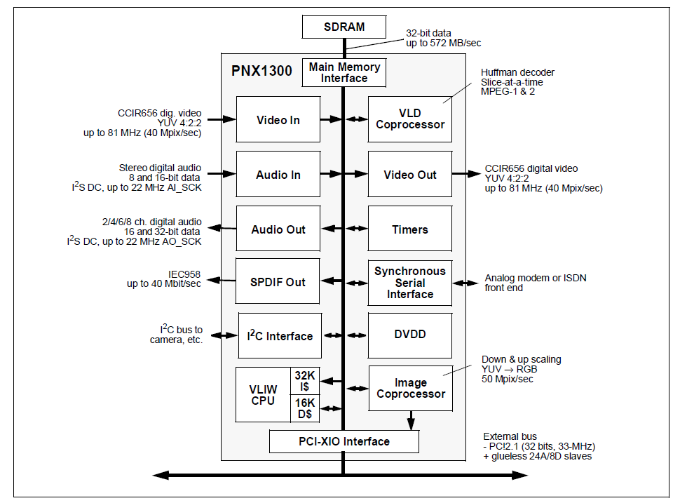
This processor has a maximum speed of 143-MHz and it works with 2.5V. Its core, called DSPCPU, is a general-purpose 32-bit CPU that also implements some media standards such as MPEG-1 and MPEG-2. The following is a block diagram of all the components of the PNX1300:
We already saw that the DSPCPU uses a VLIW (a simple explanation about this topic can be found following this link) instruction set, this allows five simultaneous operations to be issued every clock cycle. The DSPCPU has different 'issue slots', five in total, and each 'issue slot' has a different number of 'functional units', 27 in total, that can be targeted by each operation contained on each instruction. As each VLIW instruction encodes five independent operations, it is a little bit difficult to understand each instruction with respect to the others. It isn't easy to follow the control flow.
Regarding the register model of the PNX1300, it has 128 32-bit general purpose registers, starting from r0 to r127. Among these 128 registers, two that have fixed values; those are r0 and r1 that contain the integer values 0 and 1, respectively and are used mostly as boolean values, TRUE or FALSE. The programmer is not allowed to write to r0 or r1.
There is also a register for the program counter (PC) and four special registers: PCSW (Program Control and Status Word), DPC (Destination Program Counter), SPC (Source Program Counter) and CCCOUNT (Counts clock cycles since reset). The PCSW is mostly used as a register containing flags, like the EFLAGS and RFLAGS in 32-bit and 64-bit Intel platforms. It's important to remark that the PNX1300 CPU has a switchable bytesex (per unit). The bytesex switch is done by software by writing the BSX flag (bit size) into the PCSW register. This means that little and big-endian byte ordering can be found on the same execution. For example, load and store operations observe the BSX flag in the PCSW register in order to know if the operation should be done in little or big-endian order. If the BSX flag is equal to 1, then little-endian byte ordering is used. If the BSX flag is 0, then big-endian byte ordering is used.
The DPC and SPC are registers used for exception processing. The CCOUNT register, the only 64-bit register in the PNX1300, is used for cycle counting. It counts clock cycles since the last RESET event.
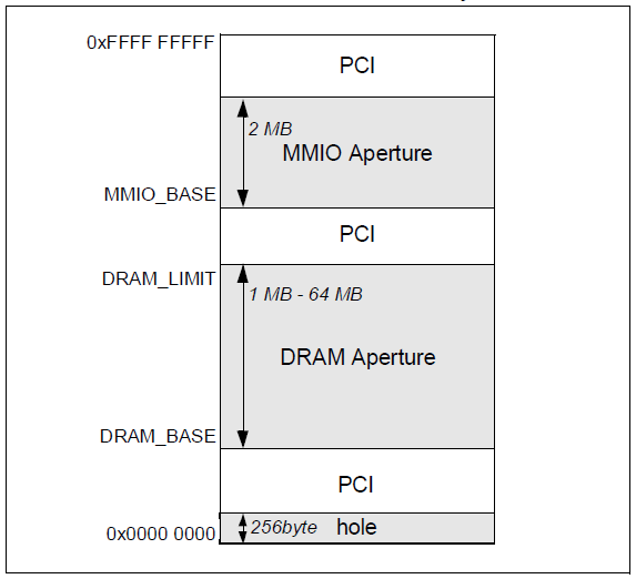
Regarding memory and MMIO, as said in the datasheet, the PNX1300 defines four apertures in a 32-bit address space: the memory hole, DRAM, MMIO and the PCI apertures. The DRAM is mapped from the address specified in the DRAM_BASE to the address in the DRAM_LIMIT registers. The maximum size is 64 MB. The MMIO is located from MMIO_BASE and is a fixed 2-MB size. Values for DRAM and MMIO are set at boot time by the BIOS. The memory hole is mapped from address 0 to 0xFF, thus is 256 bytes size. Finally, all the space not marked as DRAM, MMIO or memory hole is considered in the PCI aperture. The following is a diagram of the memory map in the PNX1300:
Now, let's go to the difficult part. I'll try to explain to you the TriMedia ASM. Be ready.
The TriMedia ASM and its instruction set
I don't know about other VLIW processors, because this is the first one I have ever dealt with, but regarding TriMedia, I'll use a phrase from a post I found [1] in order to describe its complexity regarding the assembly language:
The Trimedia processor is a VLIW machine with multiple functional units, where you can get up to 5 operations in a single instruction word. The assembler for that is a multi-pass beast that is as close to magic as I've ever encountered in an assembler.
I can attest to that, TriMedia ASM is kind of black magic mixed with some Voodoo art. Just to give you an example, here's some assembly from a TM32 processor:
(* instruction 0   : 224 bits (28 bytes) long *)
(* offset          : 0x00000000 *)
(* bytes           : 00 18 4c 0c c0 80 c0 81 c3 80 c0 b5 c0 81 02 00 12 00 8c 00 20 90 40 40 40 20 a0 d0 *)
(* format bytes    : 0x0018 & 0xff03 = 0x0000, format in little endian bit order: 00 00 00 00 00  *)
   IF r1   uimm(0x61a618) -> r0,               (* 42 bits: 0 02 30 c0 0c 4c *)
   IF r7   ijmpi(0x90030001),                  (* 42 bits: 2 40 81 81 c0 80 *)
   IF r2   fadd r67 r1 -> r32,                 (* 42 bits: 1 01 02 c0 80 c3 *)
   IF r10  bitand r64 r3 -> r16,               (* 42 bits: 0 81 02 02 81 c0 *)
   IF r1   uimm(0xd0060024) -> r0;             (* 42 bits: 3 42 83 00 12 00 *)
As in many other assembly languages from other architectures, the TriMedia ASM has instructions for mathematical operations (integer and floating point), logical, load and store data, branch, etc; the particularity is that all operations can be executed in parallel, up to five. Each operation has its own functional unit, which is basically a predefined slot in the CPU that dispatches certain group of operations. Mathematical integer operations go to the 'alu' unit, control flow operations go to the 'branch' unit, immediate operations go to the 'const' unit, etc; according to the datasheet, the PNX1300 has up to 27 functional units.
What makes TriMedia ASM difficult to understand is its encoding scheme. The instructions are compressed in a stream of variable size and the decompression unit is in charge of expanding the instructions before they are issued to the CPU.
Let's take the first instruction as an example:
IF r1 uimm(0x61a618) -> r0
You can see an 'IF' statement, before the real mnemonic, followed by the 'r1' register string. All this means that it is a 'guarded' instruction. All operations in the TriMedia CPU can be (optionally) guarded. A guarded operation executes conditionally, depending on the value of the 'guard' register. In this particular example, it means that the 'r1' (the guard register) register controls the execution of the uimm operation (The uimm operation writes the unsigned 32-bit opcode modifier n into rdest). If the r1 register 'is True' then, the value 0x61a618 is moved into the r0 register. However, in this case, there is an inconsistency in the disassembler's output. According to the official documentation, the iimm and uimm instructions are not guarded so, in this case, we can assume that the value 0x61a618 will be stored into the r0 register no matter what the value of the r1 register is.
Another important thing to highlight is the addressing modes, these can be summarized in the following table:
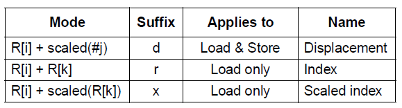
In these addressing modes, R[i] indicates one of the general purpose registers. The scale factor applied (1/2/4) is equal to the size of the item loaded or stored, i.e. 1 for a byte operation, two for a 16-bit operation and four for a 32-bit operation. The range of valid 'i', 'j' and 'k' values may differ between implementations of the architecture. The 'i' and 'k' parameters can have a value between 0 to 127. The 'j' parameter can be between -64 and 63. For example, ‘ld32d(–8) r3’ loads a 32-bit value from address (r3 – 8).
Now, how are all these operations encoded? Please, fasten your seat belts, here comes the explanation.
TriMedia ASM compression scheme
In order to understand how TriMedia instructions are encoded, I looked at the only documentation I could find about it, the "US PATENT 5787302 Software for producing VLIW instruction compression" document [2]. Also, I used the TM32 disassembler tool as mentioned early in the post to validate in some way what I was reading in the doc, and vice-versa. A better solution would have been to get the SDK or a development board in order to compile some code and disassemble/debug it using official tools but, hey!, you get what you paid for :P
To digest all the information can take some time but I encourage you to read it, it is worth it and will help you to understand what comes in the post.
General considerations
The first thing we need to learn is to make difference between an 'instruction' and an 'operation'. Each instruction in a TriMedia CPU can have up to 5 different operations. Each of these operations can belong to any of the 27 different functional units and be dispatched in the corresponding issue slot. A TriMedia 32-bit CPU has 5 issue slots. Each issue slot represents a place in the CPU where each operation is processed and has an instance of the appropriate functional unit type attached.
At this point, it is worth noting that the TriMedia CPUs are not the only ones implementing a VLIW architecture. There are others like SHARC or the C6000 processors that may have more (or less) than 5 issue slots.
The length of each instruction will vary depending on the size of each operation. The TriMedia operations size can be 26, 34 or 42 bits. These operations, as we already saw, can be guarded or unguarded, zeroary, unary or binary (0, 1 or 2 operands), can be resultless and can contain immediate parameters (7 or 32 bits). The only uncompressed operation is the branch. Each operation is accompanied by a few bits called 'format bits' that contains additional information about the operation. Format bits for an instruction are located in the prior instruction. As the TriMedia CPU has 5 operations per instruction, that means that we have a 10 format bits in total (2 for each of the 5 operation), thus, one byte plus 2 bits are used.
Format bits are a really important piece to understand how instructions are encoded. We already said that in a Trimedia CPU we have 5 issue slots and that gives us 10 format bits. As stated in the patent, we can generalize this sentence and say that there are 2*N format bits for a N-issue slot machine and these bits are organized in N groups of 2 bits. The format bits will be referred to in matrix notation as Format[j] where j is the bit number. Bits Format[2i] and Format[2i+1] give format information about the issue slot i, where 0<=i<=N. The meaning of the format bits are explained in the following table (table 1):
| Format (2i) (lsb) | Format (2i+1) (msb) | Meaning |
|---|---|---|
| 0 | 0 | Issue slot i is used and an operation for it is available in the instruction. The operation size is 26 bits. The size of the extension is 0 bytes. |
| 1 | 0 | Issue slot i is used and an operation for it is available in the instruction. The operation size is 34 bits. The size of the extension is 1 byte. |
| 0 | 1 | Issue slot it is used and an operation for it is available in the instruction. The operation size is 42 bits. The size of the extension is 2 bytes. |
| 1 | 1 | Issue slot is unused and no operation for it is included in the instruction. |
Operations correspond to issue slots in left to right order.
For example, if Format = {1, 1, 1, 1, 1, 0, 1, 0, 1, 0}, then the instruction contains three 34 bits operations ({1,0}, {1,0}, {1,0}).
As explained above, operations can have 26, 34 and 42 bits. 26-bit operations are broken up into a 2-bit part to be stored with the format bits and a 24-bit part. 34-bit operations are broken up into a 2-bit part, 24-bit part and one byte extension. 42-bit operations are broken up into a 2-bit part, a 24-bit part and two byte extensions. This means that the maximum instruction size we can have is 28 bytes (224 bits) using five 42-bit operations plus 10 format bits. If you do the math, you'll see that 42-bit * 5 operations = 210 bits -> + 10 format bits = 220 bits = 27.5 bytes, but as instructions are byte aligned, we have to add four padding bits in order to have the total 28 bytes.
Also, at the end of the instruction there is a byte-aligned group of optional 8 or 16 bit operation extension, each of them, byte-aligned. These extension bits are used to extend the size of the operation from the basic 26 bits to 34 or 42 bits, if needed.
An overview about disassembling TriMedia code
Now, the question is: how to disassemble a Trimedia instruction? This is a question I'll try to answer in the next couple of paragraphs. It wasn't easy to understand how the Trimedia ASM works (I think I still don't fully understand it :P) but I'll do my best to make a clear explanation. Needless to say, that if you find something that is not clear enough, wrong or inaccurate, just leave a comment and I'll fix it. Oh, btw, I'll be a little bit reiterative with some concepts or terms just for you to understand quite well all the explanations, I'm going to clarify things more than once because this is a very messy topic.
The first thing I have to say is that I couldn't find a very good documentation about this topic. The two sources of documentation I used were a US Patent (Patent Number 5,787,302) [2] and the PNX1302 CPU datasheet [3]. Also, I was helped with the TM32 source code [4].
The second thing I have to say is that you can't disassemble a Trimedia byte stream in an isolated way. What does it mean? For people like me, very used to Intel x86/x64 ASM, it is easy to automatically disassemble, for example, an instruction with bytes like 0xEB 0xFE (JMP EIP), however, VLIW CPUs have a compressed format that is not always so easy to understand, in fact, it wasn't. If you read the previous sections, you saw that there is a lot of information encoded in an instruction, we have format bits, byte extensions, operation code and many other information that add complexity to the disassembly process.
In the following example, I'll try to show you all the steps required to disassemble a Trimedia instruction.
The first thing to know is that the execution flow is divided into "Decision Trees" (dtree). Each Decision Tree has a given number of instructions. A Decision Tree is the scheduling unit [5] or building block for a Trimedia VLIW core, it can be seen as a function in a high-level language. In the Trimedia ASM, the beginning of a dtree is indicated with the format bytes 0xAA02, these bytes are used to encode a branch target instruction, which is the only uncompressed instruction we can find in the Trimedia instruction set. These bytes are the starting point. Then, from a high-level perspective, there are a few steps required to finally decode the instruction: get the instruction length, get the operation size, unpack the operation and decode the operation. Remember that a Trimedia VLIW instruction is composed of 5 operations, each of these operations fills one of the 5 issue slots on the CPU. It is not mandatory for an instruction to fill all the slots and in those cases a NOP (no operation) is used.
One note about branches is that they are conceived more as an instruction rather than as an operation within an instruction. This is because all the compression techniques used by the Trimedia CPU eliminate all the NOPs, however, as the branch instruction is uncompressed it needs to fill the free slots with NOPs.
Another thing I asked myself was about the byte order. According to the 'Bit and Byte order' section, little-endian is the one used. Remember that Trimedia CPUs can change the bytesex during execution by setting a bit in the PCSW register.
At this point, you should have noted that the dtree starting point will always be a branch, uncompressed, thus it will be always 224 bits length.
Now, as I said, we have some required steps to finally decode a Trimedia instruction, the first one is to get the length of the current instruction. The length is, in some way, encoded in the format bytes (first two bytes of the instruction) and gets calculated by adding the length of each operation inside plus the format bits plus the byte extensions (if there are any). The only operation that doesn't have any length is the NOP, it doesn't have any operation code either, it is only encoded in two bits (the formats bits itself, are both 1, that means that the issue slot is not used and there isn't any operation for it).
So, no matter which the formats bytes are, we should first swap the bytes to little-endian order and then start operating at bit level (shifting bits to right) in a loop of 5 iterations (because of the five issue slot), starting at 0. We shift bits in groups of two and test which is the value of each one (please, refer to table 1 in order to know the meaning of the bits). Don't forget that we should add 16 more bits for the format bytes.
There is one more thing I didn't mention before, according to the documentation, on machines with more than 3 issues slots a second group of 2-bit and 24-bit operations part is necessary. Basically, as many things in the Trimedia ASM are bit fields and everything is byte aligned, in order to decompress all instructions, some padding bits are needed. The following diagrams, extracted from the US patent, show in a more graphical way, what I'm trying to explain:
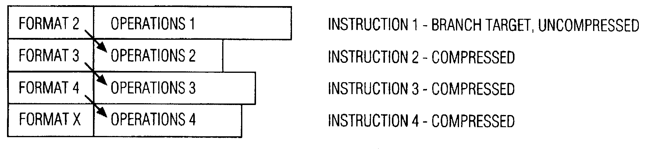
The picture above shows how an instruction is composed of different operations (4 in total) and how each operation is preceded by its format fields. Note that the only uncompressed instruction is the branch.
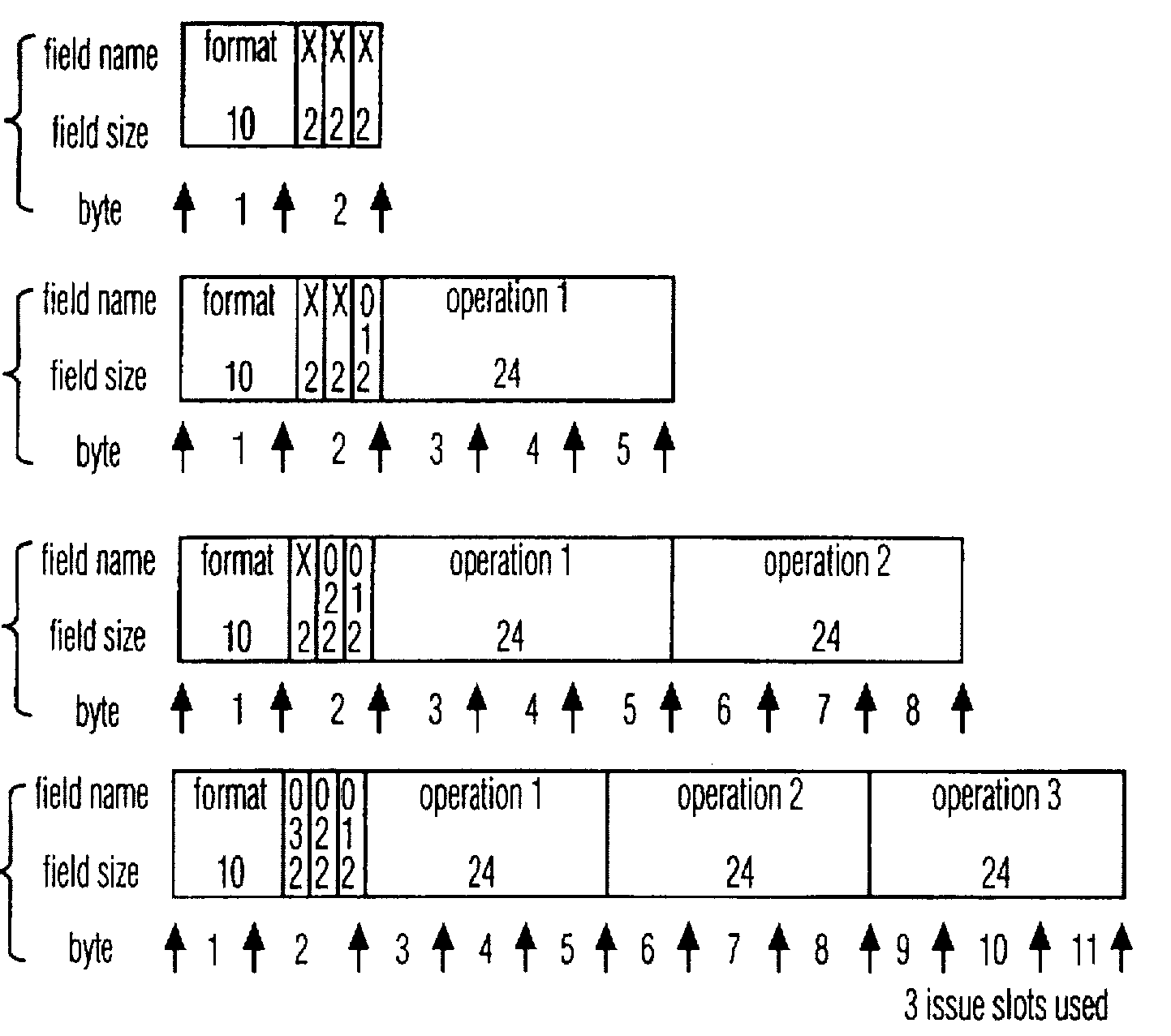
The picture above shows a set of three instructions, each of which having its field name, field size and byte field listed.
The first instruction is only two bytes, there are 10 bits for the corresponding format bits and a group of 6 bits for padding. As the instruction which has no operations inside is considered as a NOP operation.
The second instruction contains a 24-bit operation part. In this case, a 2-bit group of bits is used marked with an O.
The third instruction contains two 24-bit operation parts and two groups of 2-bit each used as padding, again, marked with an O.
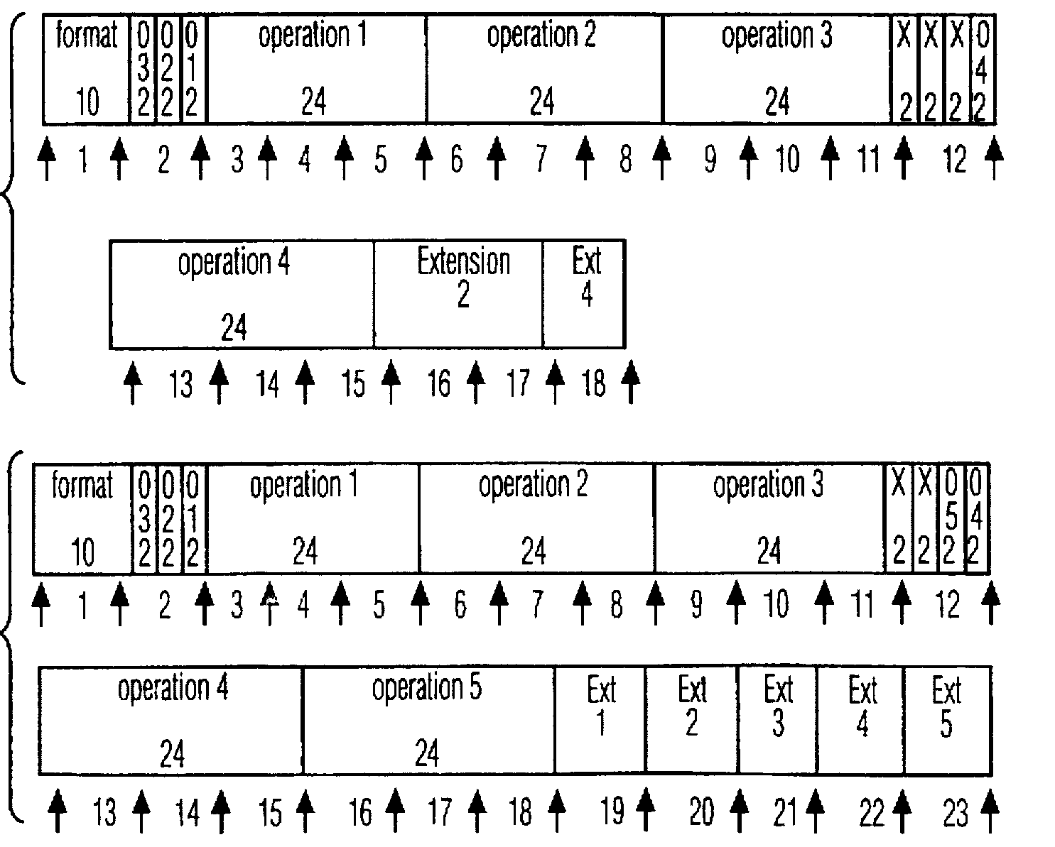
In the picture above, we have instructions with four and five operations, respectively.
The instruction with 4 operations has a first group of three operations, 24-bit part each, as we saw previously, with the corresponding 10 format bits and a group of 6 bits for padding. However, as one more operation was added, a group of 8 bits is added as format bits for the second group of operations (in byte 12) in which only the last two bits are used, marked with an O. Also, in this case, two byte extensions are added for the second operation and 1 byte extension for the fourth operation.
The instruction with 5 operation has a first group of three operations, 24-bit part each, with the corresponding 10 format bits and the 6-bit padding group. Additionally, it has the extra 8-bit format bit fields and a second group of two operations, 24-bit each. Additionally, each operation has 1 byte extension. The byte extension is placed at the end of the instruction.
It's worth noting that there is no fixed relationship between the position of the operation in the instruction and the issue slot in which it is issued. This makes possible to make an instruction shorter when not all issue slots are used.
The final steps to disassemble a TriMedia instruction are unpacking and decoding which are the most complex steps in all this mess. I challenge you to join me in the third part of this post in order to show you step by step how this process is achieved.
Conclusion
In the second part, I talked about the TriMedia architecture itself. I started by talking about the main CPU and I showed you a little bit of the TriMedia assembly and instruction set. Finally, I showed you how the decompression scheme works.
In the third part, I'll show you, with a practical step-by-step example, how all this theory works.