Author Damien Cauquil
Category Reverse-Engineering
Tags reverse-engineering, firmware, BLE, Bluetooth, hardware, smartwatch, JieLi, 2025
This blog post demonstrates how a modern variant of an hardware attack found in the 2000's allowed the extraction of a €12 smartwatch's firmware using only cheap and robust hardware. Damien and Thomas (introduced later in this post) gave a talk on this subject at this year's leHACK edition in Paris.
Introduction
It could have been a Christmas story!
We were visiting one of our local stores in December 2024 when we saw a shelf filled with tiny smartwatches in their boxes with a price label reading "€11.99/each". It was the kind of price we regularly see on AliExpress or Amazon for cheap smartwatches that are known to be scams or at least of very poor quality. This raised our suspicion, so we bought three of them to have a look once Christmas and New Year's Eve would be over.
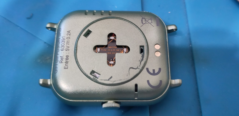
In fact, it was long after Christmas that we finally found some time to tear apart one of these watches and got our curiosity piqued. Some quick tests showed that this watch's sensors were not really good at measuring the blood pressure or track sleep activity, at least for a good reason: It appeared there were no such sensors in this watch. At least none positioned close enough to the wrist to measure light reflection as this type of sensor usually does.
Something was definitely odd about this device, and this was the starting point of a long and unexpected journey into the smartwatch's internals.
Well, let's get the firmware out of it!
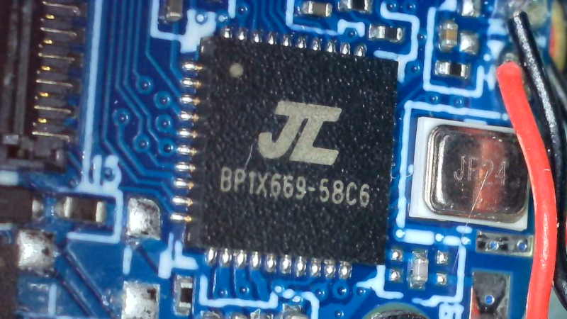
First things first, we had a look at the printed circuit board (PCB) and discovered that the device uses some a SoC from JieLi. A quick search on the Internet showed that JieLi has this bad habit of adding markings on their IC that don't directly tell what sort of chip it is 1. But at least, we knew for sure that this SoC is from JieLi, and two test points marked DP and DM on the PCB indicated how the firmware might have been flashed into the SoC (a hidden USB port exposing its two data lines usually called D+ and D-, or sometimes DP(lus) and DM(inus)).
After some research, we identified a proprietary JieLi programmer that may be able to grab the firmware out of this watch, if we could get our hands on it. We found a programmer for sale on AliExpress with a projected delivery time of about four weeks, which was way too much time to wait for someone who likes solving puzzles. We tried some DIY alternatives but none of them worked against this target.
Well, it looked like we had no other choice than to order one of these programmers and patiently wait for it to get delivered, with the hope it would work as expected and extract some valuable bytes out of JieLi's SoC.
In the meantime, we decided to try the smartwatch's official Android application and have a look at its features.
We installed it on a dedicated smartphone, followed the tutorial and got our brand new smartwatch paired with one of our phones. After some exploration we realized that unfortunately, its firmware could not be upgraded through the application.
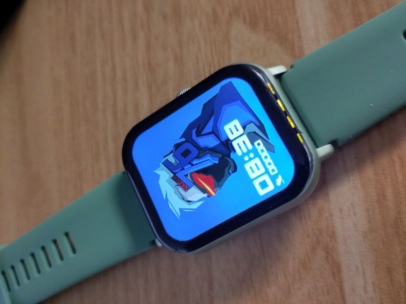
More precisely, the application does not show information about the device's firmware nor its version, but at least it features an online store where one can buy customized dials for a small amount, and even download some of them for free. We downloaded a free custom dial and managed to push it to the smartwatch. After nearly two minutes of uploading, it was satisfying to see it displayed correctly on the watch's screen.

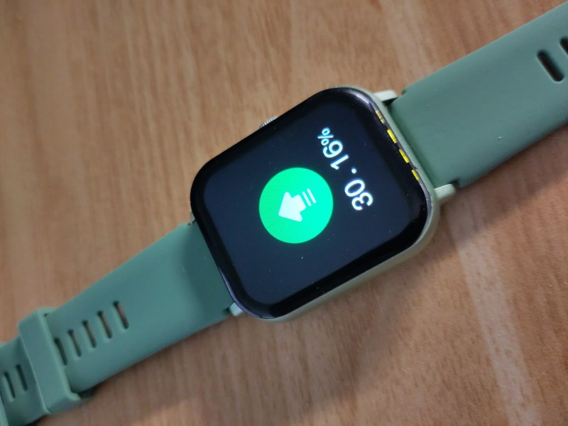
But as we watched the upload percentage slowly increase on the screen, we found it strange that such a small custom dial would take so long to upload to the watch. Using Nordic Semiconductor's nRFConnect application installed on a phone, we looked for a BLE device in the vicinity with a good signal strength and identified one that corresponded to this watch.
Well, this thing uses Bluetooth Low Energy, advertises itself and even accepts connections!
We managed to connect to it, but it was pointless since we had no idea of what data is expected by the watch or how the discovered GATT services and characteristics are used to exchange data. Bluetooth Low Energy also makes sense and explains why the upload process is quite slow with this watch, as its default MTU is 23 bytes...
Since the official application does not seem to offer a way to update our smartwatch's firmware, maybe JieLi has some kind of standard OTA feature it might rely on, we thought. We found some public Github repositories belonging to JieLi's Github account, and among them one looked very promising: Android-JL_OTA2.
An APK file is available for download, we retrieved it and installed it on our phone and searched for any compatible devices. Our smartwatch was detected as a compatible device by the mobile application, meaning it exposes at least an over-the-air update service through its Bluetooth Low Energy GATT server that we could use to access its firmware. This Android application is quite verbose and gives a lot of details about what it does during a connection to a compatible device, as shown in the logcat extract below (edited for clarity):
I ota:RcspAuth: -startAuth- device = name : null ,type : 0 ,address : 5C:C1:B9:XX:XX:XX
I ota:RcspAuth: -sendAuthDataToDevice- device : name : null ,type : 0 ,address : 5C:C1:B9:XX:XX:XX, authData : 00ABB2CDC69BB454110E827441213DDC87
D ota:OTAManager: ---onReceiveDeviceData-- >>> device : name : null ,type : 0 ,address : 5C:C1:B9:XX:XX:XX, recv data : 0161721F97C869523CCCE093D7F849CA02
D ota:RcspAuth: -handleAuthData- device : name : null ,type : 0 ,address : 5C:C1:B9:XX:XX:XX, data : 0161721F97C869523CCCE093D7F849CA02
I ota:RcspAuth: -sendAuthDataToDevice- device : name : null ,type : 0 ,address : 5C:C1:B9:XX:XX:XX, authData : 0270617373
D ota:OTAManager: ---onReceiveDeviceData-- >>> device : name : null ,type : 0 ,address : 5C:C1:B9:XX:XX:XX, recv data : 00FB610C70D43E057A45BD14BED523C190
D ota:RcspAuth: -handleAuthData- device : name : null ,type : 0 ,address : 5C:C1:B9:XX:XX:XX, data : 00FB610C70D43E057A45BD14BED523C190
I ota:RcspAuth: -handleAuthData- devAuthData : 01957EC91C20CF92F9AEBB9E206C336442
I ota:RcspAuth: -sendAuthDataToDevice- device : name : null ,type : 0 ,address : 5C:C1:B9:XX:XX:XX, authData : 01957EC91C20CF92F9AEBB9E206C336442
D ota:OTAManager: ---onReceiveDeviceData-- >>> device : name : null ,type : 0 ,address : 5C:C1:B9:XX:XX:XX, recv data : 0270617373
D ota:RcspAuth: -handleAuthData- device : name : null ,type : 0 ,address : 5C:C1:B9:XX:XX:XX, data : 0270617373
W ota:RcspAuth: -onAuthSuccess- device = name : null ,type : 0 ,address : 5C:C1:B9:XX:XX:XX,  auth ok.
W ota:RcspAuth: -handleAuthData- device : name : null ,type : 0 ,address : 5C:C1:B9:XX:XX:XX, auth ok.
W ota:OTAManager: -onAuthSuccess- >>> device[name : null ,type : 0 ,address : 5C:C1:B9:XX:XX:XX] auth ok, isBleConnected = true
JieLi's OTA application implements an authentication mechanism in what looks like a handshake, before doing anything else. Based on the captured logcat output, we can summarize this authenticated handshake as follows:
- APP sends a buffer composed of 17 bytes to the device, with the first byte set to
0x00. - Device replies with a different buffer of 17 bytes, this time starting with a byte set to
0x01. - APP sends a buffer of 5 bytes to the device, starting with a byte set to 0x02 and followed by ASCII characters that read "pass".
- Device responds with a new buffer of 17 bytes starting with
0x00. - APP sends another buffer of 17 bytes starting with
0x01. - Device responds with a 5-byte buffer starting with
0x02followed by four ASCII characters that read "pass".
From what we saw, it was quite obvious we were facing some kind of mutual authentication algorithm.
The application first initiates an authentication step, sending some data to the remote device and waiting for an answer. Based on this answer, it determines if the authentication is correct or not (in our case it sent a "pass" response to the device to notify a successful authentication).
Once the application has authenticated the device, the same mechanism is initiated by the smartwatch. The remote device answers the authentication result message previously sent by a new buffer of 17 bytes, which is received by the application that immediately responds with another buffer of 17 bytes. The watch then checks the validity of the received data and notifies the application about the result of this last authentication step with a "pass".
Once this is done, both the application and the smarttwatch know for sure that both devices are legitimate and that they can proceed with various OTA operations.
It was then clear than we needed to figure out exactly how this authentication is performed in order to play with our watch's OTA service and maybe get our hands on its firmware. It was time to dig deeper into the APK's code, and we already knew where to look thanks to the verbose output.
Digging into JieLi's OTA authentication mechanism
We started with the source code available from the JieLi's OTA Android application's repository we previously found, and identified many references to an RcspAuth class that seemed to be in charge of the mutual authentication mechanism.
The code extract below shows the main interesting parts of this file (Chinese comments have been left as they appear in the original):
// otasdk/src/main/java/com/jieli/otasdk/tool/ota/OTAManager.kt

[...]
package com.jieli.otasdk.tool.ota
[...]
import com.jieli.jl_bt_ota.constant.BluetoothConstant
import com.jieli.jl_bt_ota.constant.StateCode
import com.jieli.jl_bt_ota.impl.BluetoothOTAManager
import com.jieli.jl_bt_ota.impl.RcspAuth
import com.jieli.jl_bt_ota.model.BluetoothOTAConfigure
import com.jieli.jl_bt_ota.util.BluetoothUtil
import com.jieli.jl_bt_ota.util.CHexConver
import com.jieli.jl_bt_ota.util.JL_Log

[...]

/**
 * 用于RCSP的第三方SDK接入OTA流程
 */
class OTAManager(context: Context) : BluetoothOTAManager(context) {

[...]

    init {
        val bluetoothOption = BluetoothOTAConfigure()
        //选择通讯方式
        bluetoothOption.priority = if (configHelper.isBleWay()) {
            BluetoothOTAConfigure.PREFER_BLE
        } else {
            BluetoothOTAConfigure.PREFER_SPP
        }
        //是否需要自定义回连方式(默认不需要,如需要自定义回连方式,需要客户自行实现)
        bluetoothOption.isUseReconnect =
            (configHelper.isUseCustomReConnectWay() && configHelper.isHidDevice())
        //是否启用设备认证流程(与固件工程师确认)
        bluetoothOption.isUseAuthDevice = configHelper.isUseDeviceAuth()
        //设置BLE的MTU
        bluetoothOption.mtu = BluetoothConstant.BLE_MTU_MIN
        //是否需要改变BLE的MTU
        bluetoothOption.isNeedChangeMtu = false
        //是否启用杰理服务器(暂时不支持)
        bluetoothOption.isUseJLServer = false

        //配置OTA参数
        configure(bluetoothOption)
        RcspAuth.setAuthTimeout(5000)
        bluetoothHelper.registerCallback(btEventCallback)
        if (bluetoothHelper.isConnected()) {
            onBtDeviceConnection(bluetoothHelper.getConnectedDevice(), StateCode.CONNECTION_OK)
            if (configHelper.isBleWay()) {
                onMtuChanged(
                    bluetoothHelper.getConnectedGatt(),
                    bluetoothHelper.getBleMtu() + 3,
                    BluetoothGatt.GATT_SUCCESS
                )
            }
        }
    }

[...]
}
The init() method initializes the Bluetooth connection's parameters while most of the other methods forward any received data to the parent class, BluetoothOTAManager. This class is defined in a library called jl_bt_ota_V1.9.2-release-aar.jar available in the repository as a pre-compiled JAR file. It was time to fire up Jadx and see what was inside this library.
Decompilation failed on some parts of this library, but the com.jieli.jl_bt_ota.impl.RcspAuth class looked very interesting as it implements the authentication mechanism we were looking for. RcspAuth's startAuth() method is indeed the one that starts the authentication from the application side, by generating a 16-byte random buffer with the getRandomData() method, and sending it to the remote device prefixed with a null byte:
public boolean startAuth(BluetoothDevice bluetoothDevice) {
    boolean z;
    if (bluetoothDevice == null) {
        return false;
    }
    if (this.mAuthTaskMap.containsKey(bluetoothDevice.getAddress())) {
        AuthTask authTask = this.mAuthTaskMap.get(bluetoothDevice.getAddress());
        if (authTask != null && (authTask.isAuthDevice() || this.mHandler.hasMessages(MSG_AUTH_DEVICE_TIMEOUT)))
        {
            JL_Log.i(TAG, "-startAuth- The device has been certified or certification of device is in progress.");
            return true;
        }
        this.mAuthTaskMap.remove(bluetoothDevice.getAddress());
    }
    JL_Log.i(TAG, "-startAuth- device = " + printDeviceInfo(bluetoothDevice));
    AuthTask randomData = new AuthTask().setDevice(bluetoothDevice).setRandomData(getRandomData());
    this.mAuthTaskMap.put(bluetoothDevice.getAddress(), randomData);
    if (SUPPORT_RESET_FLAG) {
        boolean sendAuthDataToDevice = sendAuthDataToDevice(bluetoothDevice, getResetAuthFlagCmdData());

    [...]
Even if Jadx struggled decompiling the rest of this method, we noticed that once the application gets a response from the device it checks it against some authentication data returned by a call to getAuthData(), which is a wrapper that calls getEncryptedAuthData().
It was then clear what the application was doing with this first authentication step. First, it calls the getRandomData() to generate a random 16-byte challenge to send to the remote device, and effectively sends it prefixed with a null byte. Once the device responds to that challenge, the previously generated random buffer is passed to the getAuthData() method that returns the expected data if the device knew some shared secret. If the buffer sent by the device matches the one returned by getAuthData(), then the device passed the authentication check. If not, an error is returned.
This is a simple challenge-based authentication based on what appears to be a shared secret key, but we didn't have any idea about the algorithm used to compute the expected data from the generated challenge. To make things worse, we noticed that both the getRandomData() and getEncryptedAuthData() methods are implemented in a native library loaded by the RcspAuth class:
public class RcspAuth {

    // ...

    protected native boolean nativeInit();

    protected native byte[] getRandomAuthData();

    protected native int setLinkKey(byte[] bArr);

    protected native byte[] getEncryptedAuthData(byte[] bArr);

    // ...
}
As expected, a native JNI library called libjl_ota_auth.so is shipped within the APK, implementing all the cryptographic functions we were looking for. We disassembled this library in Ghidra and had a look at the two functions of interest, getRandomAuthData() and getEncryptedAuthData(). The getRandomAuthData() function generates a random buffer based on a series of calls to rand(), without even calling srand() to seed it (this is a known security problem):
void * getRandomAuthData(void *param_1)
{
  long lVar1;
  int iVar2;
  void *pvVar3;
  undefined1 local_4c;
  undefined1 local_4b;
  undefined1 local_4a;
  undefined1 local_49;
  undefined1 local_48;
  undefined1 local_47;
  undefined1 local_46;
  undefined1 local_45;
  undefined1 local_44;
  undefined1 local_43;
  undefined1 local_42;
  undefined1 local_41;
  undefined1 local_40;
  undefined1 local_3f;
  undefined1 local_3e;
  undefined1 local_3d;
  undefined1 local_3c;
  long local_38;

  lVar1 = tpidr_el0;
  local_38 = *(long *)(lVar1 + 0x28);
  local_4c = 0;
  iVar2 = rand();
  local_4b = (undefined1)iVar2;
  iVar2 = rand();
  local_4a = (undefined1)iVar2;
  iVar2 = rand();
  local_49 = (undefined1)iVar2;
  iVar2 = rand();
  local_48 = (undefined1)iVar2;
  iVar2 = rand();
  local_47 = (undefined1)iVar2;
  iVar2 = rand();
  local_46 = (undefined1)iVar2;
  iVar2 = rand();
  local_45 = (undefined1)iVar2;
  iVar2 = rand();
  local_44 = (undefined1)iVar2;
  iVar2 = rand();
  local_43 = (undefined1)iVar2;
  iVar2 = rand();
  local_42 = (undefined1)iVar2;
  iVar2 = rand();
  local_41 = (undefined1)iVar2;
  iVar2 = rand();
  local_40 = (undefined1)iVar2;
  iVar2 = rand();
  local_3f = (undefined1)iVar2;
  iVar2 = rand();
  local_3e = (undefined1)iVar2;
  iVar2 = rand();
  local_3d = (undefined1)iVar2;
  iVar2 = rand();
                    /* WARNING: Load size is inaccurate */
  local_3c = (undefined1)iVar2;
  pvVar3 = (void *)(**(code **)(*param_1 + 0x580))(param_1,0x11);
                    /* WARNING: Load size is inaccurate */
  (**(code **)(*param_1 + 0x680))(param_1,pvVar3,0,0x11,&local_4c);
  if (*(long *)(lVar1 + 0x28) == local_38) {
    return pvVar3;
  }
                    /* WARNING: Subroutine does not return */
  __stack_chk_fail();
}
The getEncryptedAuthData() function however is based on some cryptographic algorithm:
void * getEncryptedAuthData(void *pRcspAuth,undefined8 param_2,long pRandomData)

{
  long lVar1;
  long lVar2;
  void *pvVar3;
  undefined1 local_4c [20];
  long local_38;

  lVar1 = tpidr_el0;
  local_38 = *(long *)(lVar1 + 0x28);
  if (pRandomData == 0) {
    local_4c[0] = 1;
    function_E1test(BYTE_ARRAY_001055b0,1,BYTE_ARRAY_001055b6,(ulong)local_4c | 1);
  }
  else {
    (**(code **)(*pRcspAuth + 0x558))(pRcspAuth,pRandomData);
    lVar2 = (**(code **)(*pRcspAuth + 0x5c0))(pRcspAuth,pRandomData,0);
    local_4c[0] = 1;
    function_E1test(BYTE_ARRAY_001055b0,lVar2 + 1,BYTE_ARRAY_001055b6,(ulong)local_4c | 1);
    if (lVar2 != 0) {
      (**(code **)(*pRcspAuth + 0x600))(pRcspAuth,pRandomData,lVar2,0);
    }
  }

  pvVar3 = (void *)(**(code **)(*pRcspAuth + 0x580))(pRcspAuth,0x11);
  (**(code **)(*pRcspAuth + 0x680))(pRcspAuth,pvVar3,0,0x11,local_4c);
  if (*(long *)(lVar1 + 0x28) == local_38) {
    return pvVar3;
  }

  /* WARNING: Subroutine does not return */
  __stack_chk_fail();
}
We noticed that this function calls the function_E1test() function with two fixed buffers, one composed of 6 bytes and another one composed of 16 bytes. Initially, it was unclear what this E1 function was about but after some research we identified it as the E1 function defined in the Bluetooth specification and used as its legacy authentication algorithm.
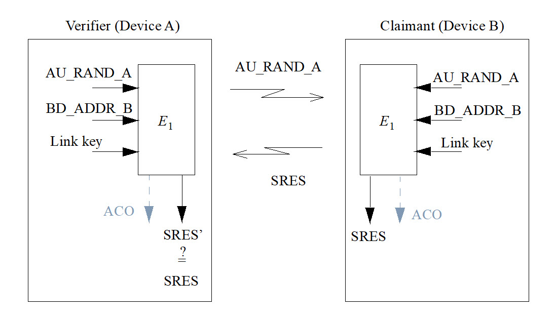
This E1 function relies on a secret 16-byte key, the identity of a device defined as its Bluetooth address (6 bytes), and a 16-byte random challenge. Our getEncryptedAuthData() function accepts a single parameter and we know for sure that it is a random challenge sent by the application, so this function must somehow reference the two other inputs to compute the corresponding SRES. The first parameter passed to function_E1test() points to a 6-byte buffer defined as follows:
        BYTE_ARRAY_001055b0                              XREF[2]:     getEncryptedAuthData:00102fbc(*),
                                                                      getEncryptedAuthData:00103000(*)
        001055b0 11 22 33        db[6]
                 33 22 11
           001055b0 [0]            11h, 22h, 33h, 33h,
           001055b4 [4]            22h, 11h
This is an hardcoded device identity corresponding to the Bluetooth address 11:22:33:33:22:11.
The second buffer corresponds to a secret key stored in this library and defined as follows:
        BYTE_ARRAY_001055b6                              XREF[3]:     FUN_00102eb0:00102f1c(W),
                                                                      getEncryptedAuthData:00102fc8(*),
                                                                      getEncryptedAuthData:0010300c(*)
        001055b6 06 77 5f        db[16]
                 87 91 8d
                 d4 23 00
           001055b6 [0]             6h, 77h, 5Fh, 87h,
           001055ba [4]            91h, 8Dh, D4h, 23h,
           001055be [8]             0h, 5Dh, F1h, D8h,
           001055c2 [12]           CFh,  Ch, 14h, 2Bh
Well, it looks like we finally figured out how the encrypted authentication data is generated!
However, we needed to find an existing implementation of E1 to save us some time. Luckily, Daniele Antonioli wrote a Python version of this function for his BIAS research paper3 and we only needed to re-use this implementation to check if the data captured in the debug output from the application matched the one produced by the recovered algorithm and its secret values:
from h import H

K = bytes.fromhex("06775f87918dd423005df1d8cf0c142b")

def ota_auth(challenge: bytes) -> bytes:
    """Compute the expected response for the given challenge, based
    on JeiLi's authentication algorithm.

    :param challenge: Challenge
    :type challenge: bytes
    :return: Computed response
    :rtype: bytes
    """
    bdaddr = bytes.fromhex("112233332211")
    _,_,_,_,response = H(bytearray(K), bytearray(challenge), bytearray(bdaddr), 6)

    # Return the computed challenge response
    return response

if __name__ == "__main__":
    challenge = bytes.fromhex("ABB2CDC69BB454110E827441213DDC87")
    print(f"Challenge: {challenge.hex()}")
    response = ota_auth(challenge)
    print(f"Encrypted Auth data: {response.hex()}")
    expected = bytes.fromhex("61721F97C869523CCCE093D7F849CA02")
    print(f"Expected encrypted auth data: {expected.hex()}")
    if expected == response:
        print("JieLi auth OK!")
    else:
        print("Oops, JieLi auth failed.")
When we ran this Python script, we were pleased to see that the computed value was exactly the same as the one returned by the watch!
$ python3 auth.py
Challenge: abb2cdc69bb454110e827441213ddc87
Encrypted Auth data: 61721f97c869523ccce093d7f849ca02
Expected encrypted auth data: 61721f97c869523ccce093d7f849ca02
JieLi auth OK!
The use of the Bluetooth's E1 legacy authentication function with two hardcoded secret values turned this function into some kind of hashing function. This does not protect at all against man-in-the-middle. replay or TOCTOU attacks, as an attacker doesn't even need to know these secret values:
All they need is a legitimate smartwatch to forward the challenge to and get the response from to make the target application believe any spoofed device is a legitimate one.
We replicated this authentication mechanism using a Python script based on WHAD4, and managed to successfully perform the handshake. We then dug into JieLi's OTA features, but after looking for some interesting piece of code, we had to face the hard truth: there is no way to retrieve the firmware from the device through OTA!
Did we reverse this authentication mechanism for nothing, just to discover afterwards that this OTA feature could not be used to extract the device's firmware? Definitely.
Failure is always an option
This kind of failure happens from time to time. We were so hypnotized by the idea of getting privileged access to the device through its dedicated firmware upgrade feature, that we completely forgot to take a step back and think. We dived deep into what we thought would give us access to this piece of code we were looking for, until it failed.
But in cybersecurity, we know for sure there is always a way to break in and access the information we need, even when nothing seems to work as expected. Because this is exactly when we think we may not be able to get what we want that creativity kicks in, and sometimes brings unexpected solutions to unexpected problems.
In Silence on the wire5, a book written by Michal Zalewski (who also goes by the handle lcamtuf) and published in 2005, there is this cool story about an unexpected data leakage through blinkenlights.
In 2002, Joe Loughry from Lockheed Martin Space Systems and David A. Umphress from Auburn University published a research paper entitled Information Leakage from Optical Emanations6 revealing that many network devices were leaking data... through their traffic monitoring LEDs. These LEDs were often called blinkenlights, a name coming from an old WWII joke, and most of them were simply driven by the transmit and receive data lines of such equipment.
What a better way for monitoring traffic than seeing it with your own eyes? Anyone with an apparatus able to capture the light emitted by those LEDs could easily recover all data going through, no physical access required. This design weakness was present in various network equipment they discovered, and nobody thought it was a very bad design idea until this paper was published.
JieLi's OTA feature does not want to let us in? Nevermind, we will find another way to retrieve this smartwatch's firmware.
We decided to focus on the watch's custom dials, as there should be some specifically formatted data we could modify, and see where that would lead us to. It took some time to find a vulnerability and determine how to exploit it, but we were not expecting this blinkenlights story to be the spark that allowed us to successfully extract the watch's firmware!
Capturing dials sent over the air
We first made the hypothesis that those dials, since they seem to be animated, may contain some code to implement the logic of these animations. If there was code in dials, then it would be easy to patch one of them to get some arbitrary code executed, after guessing the main CPU's architecture. To achieve this, we needed to know how those dials are formatted and how they are indeed sent to the watch and figure out a way to abuse this feature.
We managed to capture the data sent by the mobile application during an upload of a free dial with WHAD into a PCAP file, analyzed the exchanged data and noticed something familiar:
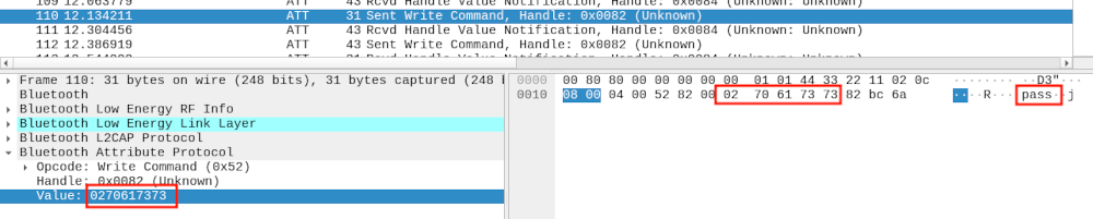
The data sent by our smartwatch through a BLE notification, 0x02 0x70 0x61 0x73 0x73, rang a bell. It was the exact same data we received from the watch when performing the OTA authentication with JieLi's OTA Android application! A quick look at the data exchanged between the Android application and the smartwatch revealed that it was the exact same authentication mechanism used prior to upload a custom dial, and we were lucky to have reverse-engineered this mechanism and implemented some Python script to mimick it.
Once this authentication step is performed and the application authorized by the smartwatch, the dial is sent over BLE through a series of write operations performed on a specific characteristic. The first write operation specifies the number of data chunks that will follow, and the next writes transmit the dial file's content by blocks of 16 bytes. The upload process is slow as the application only sends 16 bytes of data at a time, and depending on the Bluetooth Low Energy connection's settings it may vary from one smartphone to another. The first write operation sent by the application to the watch is structured as follows:
| Offset | Size | Value | role |
|---|---|---|---|
| 0x00 | 3 | 0xAB 0x06 0x28 | Magic bytes |
| 0x03 | 2 | N | Number of chunks (big endian) |
| 0x05 | 1 | C | Dallas 8-bit CRC, computed on previous bytes |
Each chunk sent after this header follows this structure:
| Offset | Size | Value | role |
|---|---|---|---|
| 0x00 | 2 | 0xAB 0x29 | Magic bytes |
| 0x02 | 2 | N | Chunk ID starting from 0 (big endian) |
| 0x05 | 16 | Data | Chunk data |
Once the last chunk is received, the smartwatch sets the received dial as its custom dial and displays it. After having figured out how a dial is sent over BLE, we wrote some Python script to extract the header and all the chunks sent by the application and saved the recovered data into a file for further analysis. We did the same for different dials in order to perform a differential analysis, based on the fact the more different types of dials we have the easiest it would be to guess the generic structure they follow.
Understanding dial's file format
With the few binary files collected from dials sent to the smartwatch, we compared their structure and figured out their different fields and some of their meanings. Before going into the details of this structure we must warn our readers that our original hypothesis regarding these dials - the fact they may contain active code executed by the smartwatch - was quickly destroyed when we had a look at the collected files.
In fact, our analysis revealed that no code was required to animate those dials, as the animated parts were simply one of the many features supported by the smartwatch. But we kept reverse-engineering this format as parsers are generally prone to malformed data and sometimes could be abused to achieve code execution.
Dials are composed of different types of regions, each region describing an item to show on screen. We identified some of these region types during our analysis, including but not limited to:
- hours: displays the number of hours in a 2 digit format with a specific font.
- minutes: displays the number of minutes in a 2 digit format with a specific font.
- animated clock: renders a ticking clock, including hour and minute needles as well as the clock body.
- battery level: renders a graphic representation of the current battery level.
- simple picture: displays an image on screen.
Each region has its own coordinates, width and height encoded in a dedicated header, as well as other information depending on its type (color indicating transparency, alpha channel, format of pixels in image, etc.). The example below shows how these regions are defined right after a fixed header, and where the data associated with those regions is stored.
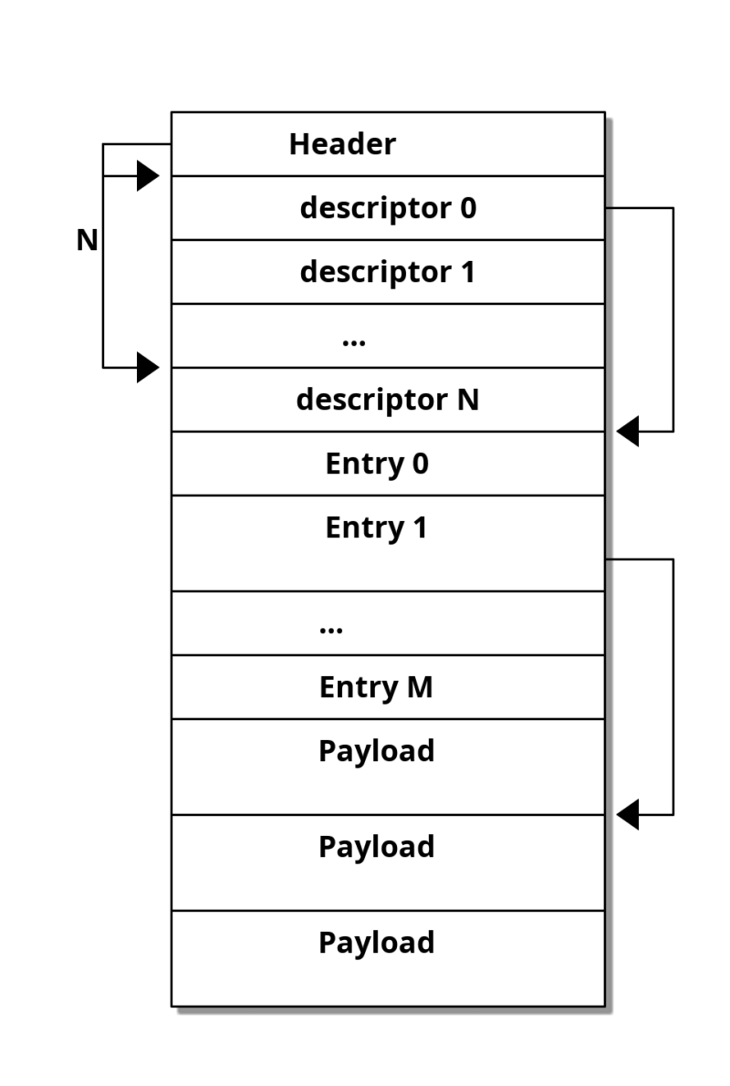
We noticed an interesting characteristic in this format: the headers use offsets to locate other pieces of information that the firmware must parse to render the dial correctly. From experience, we know that using such offsets requires strict boundary checks to avoid reading out of the dial's binary content, and these checks are sometimes poorly implemented or simply missing. We thought it might be a good first test to run against the watch, but we first needed to craft a small custom dial of our own.
Fun with dials
Our analysis of the dial data format gave us a lot of information about how to create one from scratch. We decided to craft a special one to check if our understanding of both a dial's format and the way it is sent over BLE were correct, with the intended goal of showing a carefully selected picture on the tiny screen of our smartwatch. If this worked as expected, then we would be able to have fun with those offsets.
A standard image defined in a dial can be encoded using various formats, we decided to go with the one we identified in a high quality dial, using an image encoded in RGB565 (64k colors). The RGB565 pixel format is pretty standard in the embedded world and especially well-known from developers that create code to draw on TFT or OLED screens.
Each pixel's color is defined by the quantity of the three primary colors of light: red, green and blue. Those colors are mixed altogether based on the quantity defined for each of them to produce the required color. A 24 bits-per-pixel bitmap will encode the quantity of red, green and blue of each pixel on 8 bits each, resulting in a pixel stored on 3 bytes, or 24 bits.
The RGB565 pixel format uses a different encoding based on 5 bits for red and blue and 6 bits for green, resulting in a 2-byte or 16 bits value per pixel. This format is easier to manipulate and images require less memory to be stored. We converted our carefully selected picture found on the Internet into its RGB565-encoded version, after having it cropped to the screen size, and created a custom region in our special dial.
We generated a valid header based on this image and ended up with what looked like a valid dial designed to only show our picture on screen.
#!/usr/bin/env python

# Code by Xilokar and Virtualabs

import sys
import argparse
from struct import pack
from PIL import Image

TYPE_UNKNOWN = 0x01
TYPE_LABEL  = 0x0a

WIDTH = 240
HEIGHT = 286

def to_rgb565(r, g, b) -> list:
    """Convert pixel to RGB565 format

    /-- B0 -----\/--- B1 ----\
    7           0 16         8
    [G(3) | B(5)][R(5) | G(3)]
    """
    b0 = (b>>3) | (((g>>2) & 0x07)<<5)
    b1 = (g>>5) | ((r>>3)<<3)
    return [b1, b0]

def image_to_rgb565(path):
    """Convert a PNG into a RGB565 image as a byte array.
    """
    img = Image.open(path)
    print(img)
    w,h = img.size

    # Check image size (must be 240x286 pixels)
    assert w == 240
    assert h == 286

    # Convert pixels into RGB565 array
    rgb565 = []
    for y in range(h):
        for x in range(w):
            # Grab pixel
            r,g,b,a = img.getpixel((x, y))

            # Convert pixel to RGB565 16-bit value
            rgb565 += to_rgb565(r,g,b)

    return rgb565

if __name__ == "__main__":
    # Read our Rick Astley image in RGB565
    rick_rgb565 = bytes(image_to_rgb565("rick.png"))

    # Generate our file header
    #
    # We have a generic 8-byte header followed by two 14-byte long section
    # descriptors. The first section descriptor is mandatory and point to
    # a null memory region (discarded by the wath).
    # The second descriptor defines a RGB565 encoded bitmap, that follows our
    # header and section descriptors.

    # We compute our header (2 section descriptors)
    header = pack("<HHHH", 0x4, 0x2, 0x1, 2)
    header_size = 8 + 2*14

    # We generate our first section descriptor (unknown, mandatory)
    first_item_desc = pack("<BBHHHHI", TYPE_UNKNOWN, 0xfe, 0x01, 0xf0, 0x11e, 0x1f, header_size)

    # We create a fake body for the first section
    first_item_body = b"\x00" * (0x2ee - 0x1f6)

    # We generate our second section descriptor (image, RGB565)
    second_item_body_offset = header_size + len(first_item_body)
    second_item_desc = pack("<BBHHHHI", TYPE_LABEL, 0x04, WIDTH, HEIGHT, 0x02, 0x01, second_item_body_offset)

    img_offset = header_size + len(first_item_body) + 24
    second_item_body = pack("<HBBHHIIII", 0xffff, 0x01, 0x83, 0x0, 0x0,
        img_offset, WIDTH*HEIGHT*2,
        img_offset, WIDTH*HEIGHT*2)

    # Build our final file
    content  = header
    content += first_item_desc
    content += second_item_desc
    content += first_item_body
    content += second_item_body
    content += rick_rgb565

    # Output to file
    with open("rick-watchface.bin", "wb") as face:
        face.write(content)
This script produced a custom dial that we needed to upload to our smartwatch. We wrote another Python script using WHAD that connected to the watch, performed the mandatory authentication step and eventually uploaded the dial following the format we recovered from our previous analysis. Unfortunately, our first try ended up in a timeout as it took too long to send the whole picture, and the smartwatch rejected our upload. After too much time spent investigating the matter, we found a way to speed things up by forcing WHAD to use a very short hop interval value when initiating a connection to our smartwatch, resulting in shorter connection events and therefore a faster upload speed.
The final upload process is showed below (video has been edited, upload speed has been improved but is still slow):
We knew at this moment that our work on reverse-engineering the dial format and the associated upload process was correct, and that it was time to move on to more interesting ideas, like playing with those offsets we previously noticed. We decided to fuzz them a bit and see how a dial with an image pointing to a bad offset would be decoded and what could be the result on screen.
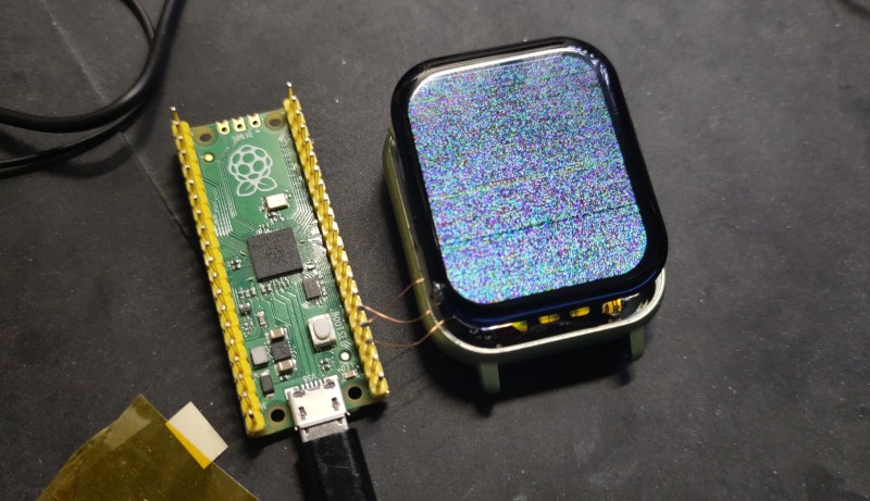
Targeting an RGB565 image region was the simplest thing to do, as we had a script to generate a dial containing such a region and the only thing we had to change was a specific offset value. Also, targeting the pixel data of an image displayed on screen would cause the screen to show arbitrary data if by chance the offset corresponds to a valid memory address and the firmware blindly read data and transfered it to the screen. Thomas Cougnard (also known as Xilokar), who had been following our progress so far, decided to join us and found some specific offset values that did not brick the device and led to some weird images displayed by the watch:
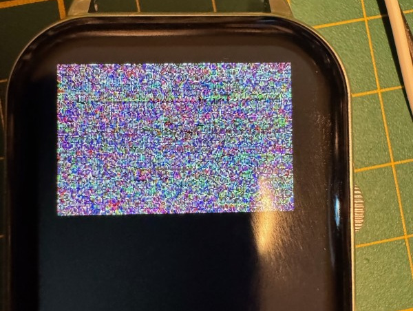
As expected, the parser did not check if the specified offset pointed outside of the dial's binary data and simply considered that was the expected image's pixel data and sent it to screen. When we saw this, we knew exactly what to do to extract this smartwatch's memory and get our hands on the firmware... Blinkenlights!
Blinkenlights attack revival
This time, we had a TFT screen showing some pixels encoded using the standard RGB565 format, directly taken from the SoC's memory, instead of LEDs.
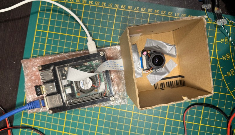
A TFT screen embeds a small controller that drives a matrix of RGB LEDs, using its own temporary memory (RAM) to store the screen state and a specific protocol to allow an external system to drive the screen and set pixels at a specific rate. Thomas opted for an optical attack like the original paper, targeting the screen's LED matrix and creating a specific rig to extract data from all those LEDs (which is far more complex than what the authors of the original paper used during their research). He set up a specific rig to capture the displayed pixels and infer the data sent to the screen, but also had to play with the dial image's resolution to ease data recovery.
In the meantime, Damien took another path, as TFT screens rely on well-known controllers like Sitronix's ST7789 or Ilitek's venerable ILI9341, but sometimes also on different or unknown controllers that speak different languages, electronically speaking.
If we managed to figure out which controller was present in the smartwatch's screen and to capture the data sent by the SoC to this controller, we would had been able to capture the pixels sent to our screen and therefore to dump the content of any arbitrary memory region, like others did with those old network's cards and their LEDs but without all the issues caused by those tiny RGB LEDs and any bias introduced by a complex optical sensor.
This attack was pretty simple to perform on paper, but also had some practical limitations we needed to figure out:
- At what speed those pixels are sent to the screen?
- Is it a serial or a parallel interface used by the SoC to control the screen?
- How are the pixels sent to the screen and in which order?
There was no other way to find out than to connect a logic analyzer to the screen data lines, by soldering multiple .1mm diameter wires to the connector and analyzing the data sent back to the screen. The screen connector's pinout was unknown, so we first tried to determine how the controller was connected to the SoC, given the fact our logic analyzer was a cheap one (the best one being unavailable at this time). We managed to capture some data when sampling at 8 Ms/s, but the decoded data made no sense. This was due to the high frequency on this communication bus that left our logic analyzer way out of sync. We used a Raspberry Pi Pico as an alternate logic analyzer, thanks to Agustín Gimenez Bernad's 100 Msps Pico-based logic analyzer project7.
This time, we captured the suspected data lines with a 100 Ms/s rate and successfully decoded some standard TFT screen commands supported by a wide range of controllers. In fact, the SoC uses a 25 MHz clock to drive the screen, which is pretty fast.
The screen controller has been guessed from its specific device ID response sent when it receives a Read Display ID command (0x04), namely a NV3030B screen controller. Once the controller known and the interface pinout and speed determined, the only thing we had to do was to decode every command related to a screen update operation and capture the data. Thomas tested different setups but failed at getting a decent optical sensor able to extract reliable data from pixels on screen. Since Damien's setup was somehow getting data that could be interpreted as valid commands, they agreed to use it to get the firmware out of the watch.
Extracting bytes from screen updates
We used the same Raspberry Pi Pico to capture the data sent by the main SoC to the screen because this tiny microcontroller has a lot of advantages:
- it can be overclocked to 200 MHz (it has officially been tested at 200 MHz and proven stable by the Raspberry Pi Foundation)
- it provides a pretty neat feature to perform low-level decoding called PIO
- it features a more than decent amount of RAM (264 kB)
- its development environment and related toolchain are well-known and easy to use
Our idea was to sniff the data sent to the screen with a dedicated PIO program, save it into RAM and then send it to our host computer once the data recovered through the Pico's serial port exposed through its USB connector. We wrote the following PIO program to sample a bit on the screen's serial data line each time we see a raising edge on the clock line, and bits are pushed inside an internal 32-bit shift register:
; Screen data sniffer
;
; Fetch bits when raising edge on clock

.define gpio_clock 3

.program sniff

    wait 1 gpio gpio_clock  ; wait clock to go high (rising edge)
    in pins, 1              ; read 1 bit from mapped GPIOs and feed ISR
                            ; autopush set to 32, read bytes will be automatically
                            ; sent to RX FIFO


% c-sdk {
// this is a raw helper function for use by the user which sets up the GPIO output,
// and configures the SM to output on a particular pin

void sniff_program_init(PIO pio, uint sm, uint offset, uint data_pin, uint dcx_pin) {
   // Set data and dcx pins as pio
   pio_gpio_init(pio, data_pin);
   pio_gpio_init(pio, dcx_pin);

   pio_sm_config c = sniff_program_get_default_config(offset);
   sm_config_set_in_pins(&c, data_pin);
   sm_config_set_jmp_pin(&c, dcx_pin);
   sm_config_set_in_shift(&c, false, true, 32); // autopush after 32 bits received
   pio_sm_init(pio, sm, offset, &c);
}
%}
Since the interface bus is clocked at 25 MHz and it takes some cycles for this PIO program to be run, we had to keep it as small as possible. In fact, this program is composed of two instructions:
- a wait instruction waiting for a rising edge on the clock GPIO (configured as an input)
- a read on the data GPIO, that is then clocked in a 32-bit internal shift register
In the meantime, the clock line is back to a low logic level and the next wait is blocking until the next clock's rising edge. This allows sampling 32 bits from the interface bus as fast as possible, and the Pico's main program only has to wait for each 32 bits values acquired by our PIO program and save them in RAM:
#include <stdio.h>
#include <string.h>

#define SYS_CLK_MHZ 200

#include "pico/stdlib.h"
#include "hardware/pio.h"
#include "hardware/uart.h"
#include "hardware/clocks.h"
uint32_t  g_clckdiv = 0;
#include "sniff.pio.h"

#define BUFFER_SIZE 145000

static uint8_t buffer[BUFFER_SIZE];


void sniff_pin_forever(PIO pio, uint sm, uint offset, uint data_pin, uint dcx_pin) {
    sniff_program_init(pio, sm, offset, data_pin, dcx_pin);
    pio_sm_set_enabled(pio, sm, true);
}


int main()
{
    uint8_t host_cmd;
    int iter;
    uint32_t data,*pd;

    /* Clear buffer. */
    memset(buffer, 0, BUFFER_SIZE);

    stdio_init_all();

    // PIO Blinking example
    PIO pio = pio0;
    uint offset = pio_add_program(pio, &sniff_program);

    /* Configure program to use GPIO 2 as data in and 4 as DC/X. */
    sniff_pin_forever(pio, 0, offset, 2, 4);

    while(1) {
        // Acquire data from PIO
        pd = (uint32_t *)buffer;
        while (pd < (uint32_t *)(buffer + BUFFER_SIZE)) {
            // Wait for PIO to send a byte
            *(pd++) = pio_sm_get_blocking (pio, 0);
        }

        // send capture bytes to uart
        for (int j = 0; j < (BUFFER_SIZE/4); j++) {
            printf("%02x%02x%02x%02x", buffer[j*4+3], buffer[j*4+2], buffer[j*4+1], buffer[j*4]);
        }
    }
}
The buffer used to save data captured from the screen interface has a capacity of 145000 bytes in order to leave some memory available while allowing enough data to be collected to grab a full screen update from the main SoC. Once the buffer fills, it is sent in hexadecimal form to the host computer through its CDC ACM serial port, which is pretty fast even if virtually clocked at 115.200 bauds.
On the host computer, we ran a small Python script designed to collect the data sent back by the Pico and save it as a binary blob in a target file. It was then easy to collect the data sent when a screen with a bad offset was sent to the smartwatch and displayed and investigate this data to determine how the system updates the screen.
We identified a pattern that is quite common with TFT screens based on three commands used to set the column and page addresses (using respectively 0x2A and 0x2B as their command byte), followed by a command used to send the pixel data corresponding to the specified region (0x2C):
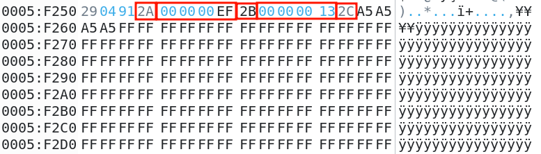
Rebuilding the whole firmware image
We had everything we needed to capture all the pixels's data sent to screen and therefore to extract the firmware, we only needed to design a set of tools to capture portions of memory and then rebuild the whole firmware from them.
First, we designed a specific header in order to quickly identify the data corresponding to the top of the screen, making it starting and ending with some magic bytes and occupy the top two lines of the screen. We also added into this header the memory address corresponding to the address of the data read by the firmware and sent to screen, based on our probable guess. We wrote a dedicated Python function to generate this:
# Syncword is used to locate the first line
syncword = 0xa5a5a5a5

# This is the memory address we want to dump
address = 0x00000000

#First line
image_01_data  = pack("<I", syncword) + b"\xff\xff" * (w - 2)
# second line
image_01_data += pack("<II", 0xdeadbeef, address)
image_01_data += b"\xff\xff" * (w - 6)
image_01_data += pack("<I", 0xdeadbeef)
This small structure will be dumped by our tool and found at the beginning of the extracted data, allowing us to check that we did not have any bit shift based on both the defined synchronization word and trailing magic bytes 0xdeadbeef, but also to recover the address associated with the captured data. This Python code was used to generate a set of valid dials for successive memory addresses that were uploaded one after the other while we dumped the data sent to the screen with another python script:
import sys
from struct import unpack
from serial import Serial
from time import sleep

# Open serial port and collect data. press CTL-C to process.
sniffer = Serial("/dev/ttyACM0", 115200)
content = b''
while True:
    try:
        buf = sniffer.read(4096)
        if len(buf) > 0:
            content += buf
            sys.stdout.write("[i] Collected %d bytes\r" % len(content))
    except KeyboardInterrupt:
        break

# Decode hexa to bytes
print("[i] Decoding collected bytes ...")
content = bytes.fromhex(content.decode('latin-1'))
print("[i] Captured %d raw bytes" % len(content))

# We need to find each chunk
data = b""
offsets = []
blocks = {}
nblocks = -1
for i in range(len(content)-11):
    if content[i]==0x2a and content[i+5]==0x2B and content[i+10]==0x2c:
        x = unpack(">I", content[i+1:i+5])[0]
        y,z = unpack(">HH", content[i+6:i+10])
        print("found data @ 0x%08x (%x,%x)" % (i+11, x, y))
        if z==0x13 and x==0xef:
            offsets.append(len(data))
            nblocks += 1
            blocks[nblocks] = [y]
        elif x == 0xef and nblocks >= 0:
            blocks[nblocks].append(y)
        data += content[i+11:i+11+9600]

# Check if we have a complete block
found = False
for i,offsets in blocks.items():
    if len(offsets) == 15:
        print("[i] Found a complete image block at offset 0x%08x, extracting ..." % offsets[i])
        img_data = data[offsets[i]:offsets[i]+137280]
        found = True
        break

if found:
    # Check image data
    if img_data[:4] == b"\xa5\xa5\xa5\xa5" and img_data[0x1e0:0x1e4] == b"\xef\xbe\xad\xde":
        if img_data[0x3bc:0x3c0] == b"\xef\xbe\xad\xde":
            addr = unpack("<I", img_data[0x1e4:0x1e8])[0]
            print("Found valid dump for address 0x%08x" % addr)
            open("dumps/firmware-dump-0x%08x.bin" % addr, "wb").write(img_data[0x3c0:])
else:
    print("[!] No image frame identified.")
We managed to extract the firmware slice after slice, each slice ended up in a dedicated file. Once all the files gathered, we wrote a final script to rebuild the whole firmware in a single binary file that would allow us to analyze it and later disassemble it:
"""List extracted data blocks and rebuild the whole memory image.
"""
import sys
import os
import re
# Pick target dir
target_dir = sys.argv[1]
memimg = sys.argv[2]
# Collect blocks filenames from dir
blocks = [f for f in os.listdir(target_dir) if os.path.isfile(os.path.join(target_dir, f))]
# Extract addresses and content from filename
map = {}
for f in blocks:
res = re.match("^firmware-dump-0x([0-9a-f]{8}).bin$", f)
if res is not None:
address = int(res.group(1), 16)
content = open(os.path.join(target_dir, f), "rb").read()
map[address] = content
# loop for holes in map
address = 0
count = len(map.keys())
memory = b''
while count > 0:
if address in map:
memory += map[address]
count -= 1
address += len(map[address])
else:
print(f"[!] Missing content for address 0x{address:08x}")
break
if count == 0:
print(f"[i] Map is complete, saving to {memimg} ...")
with open(memimg, "wb") as img:
img.write(memory)
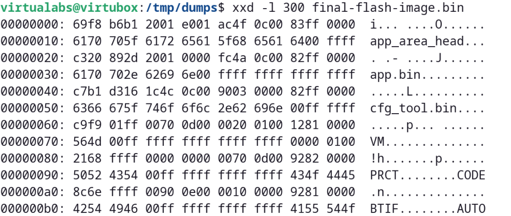
print(f"[i] Written {len(memory)} bytes to {memimg}.")
And we ended up with what looked like a 2 MB firmware file that matches some regular JieLi firmware as specified in Kagaimiq's documentation.8
Conclusion
This cheap smartwatch based on some obscure system-on-chip gave us a hard time figuring out how to extract its firmware. We could have used the official programmer sold by JieLi but since we could not afford waiting several weeks to get our hands on it, we found an unexpected way to get access to the firmware by exploiting an out-of-bounds read combined with a custom rig based on a cheap Raspberry Pi Pico.
It was a very good opportunity to test the limits of a Pico overclocked at 200 MHz but also to use its powerful programmable inputs/outputs (PIO) to speed things up. We could have used an expensive logic analyzer to capture screen updates and decode data from them, but in the end we found this solution easier to set up as it only requires a few lines of C and Python to implement an efficient capture rig that costs almost nothing.
It also demonstrates once more that cheap hardware can often be used to achieve attacks on embedded systems, and that some old tricks used to leak data out of a system are still useful when facing recent technology!
With the firmware successfully extracted from the system-on-chip's memory, the fun part could start: identifying functions in charge of measuring and showing on screen the vitals and figuring out how those values are calculated, but that's a story for another time 😉.
Acknowledgements
We'd like to thank Thomas Cougnard (Xilokar) for his collaboration on this unexpected study of this smartwatch and for the ups and downs he went through while testing random offsets, almost bricking his watch multiple times (he eventually managed to bring it back to life). We also would like to thank Kagaimiq for the awesome documentation they released on their Github repository, that helped a lot to figure out how JieLi's SoCs are designed and how one can interact with them, as well as the various data formats used by most chips.
References
-
Chip markings explained, Kagaimiq, https://kagaimiq.github.io/jielie/chips/chip-marks.html ↩
-
Jieli's Android OTA application repository, Github, https://github.com/Jieli-Tech/Android-JL_OTA ↩
-
Bluetooth Impersonation Attacks, Daniele Antonioli, https://francozappa.github.io/about-bias/ ↩
-
WHAD framework, Damien Cauquil & Romain Cayre, https://whad.io ↩
-
Silence on the wire, Michal Zalewski, No Starch Press, 2005, https://nostarch.com/silence.htm ↩
-
Information Leakage from Optical Emanations, Joe Loughry & David A. Umphress, 2002, https://dl.acm.org/doi/10.1145/545186.545189 ↩
-
LogicAnalyzer, Gusmanb, https://github.com/gusmanb/logicanalyzer ↩
-
Jieli's new firmware format, Kagaimiq, https://kagaimiq.github.io/jielie/datafmt/newfw.html ↩