Author Guillaume Heilles
Category Hardware
Tags automotive, training, PCB, KiCAD, hardware, 2019
In this article we describe how we created a low cost training Electronic Control Unit (ECU) that can be attacked at will, without damaging a real car. The whole project is open-source on Quarkslab's github page.
Context
When we first started hacking into real cars a few years ago, one of our main concerns was to avoid damaging them. As it turns out, it's pretty difficult to do it by fuzzing on the CAN bus, but it can happen if you push your luck a bit too much. More about that later.
When we decided to propose a training about practical car hacking, it was clear that we could not let all the attendees play with a real car. It's very important to practice on a real one, so we kept this part of the training. However, another approach was needed to let attendees play and experiment with an ECU, which is why we designed and created a simple training ECU.
While this ECU was not perfect during the first training sessions, we managed to improve it and make it more stable after a few iterations. We will explain in this article what the current training ECU looks like.
A similar approach is proposed by Toyota. Their training ECU is called PASTA and as of this writing, is announced to be published on github. It contains fancier stuff but might be more expensive than our design. We wanted to keep our ECU simple and inexpensive, so that each attendee could have one during the training.
We think this approach is great so we decided to opensource both the latest software and the hardware of this project. If you like it, you can contribute to the software or register to the training to practice on the ECU through guided exercises.
Minimalistic ECU
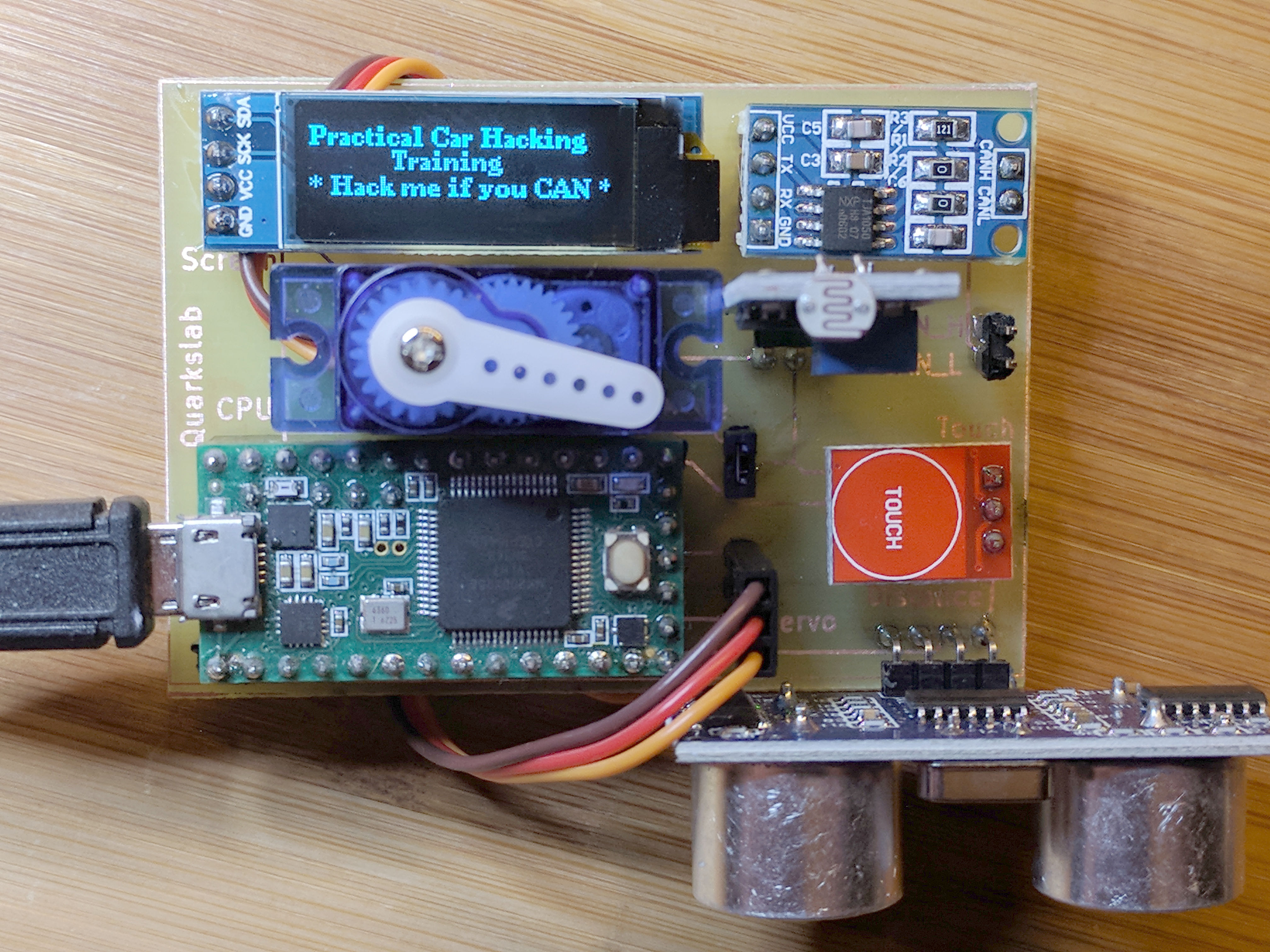
A minimalistic ECU is composed of a microcontroller, a CAN controller, a CAN transceiver, and a few sensors and actuators. In order to keep things easy and simple, we decided to buy and assemble different modules gathered on a single PCB.
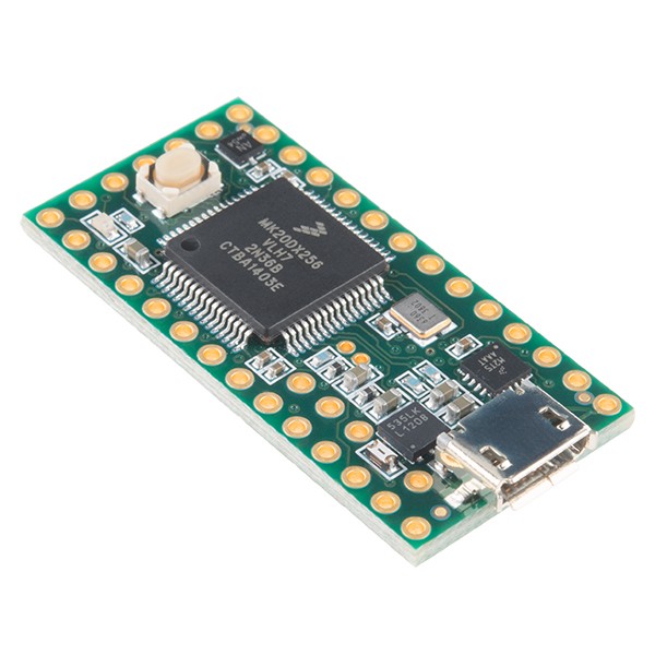
Microcontroller
For the microcontroller, we chose a Teensy3.2 board, as it already contains a CAN controller. We used the FlexCAN library from Collin80 on github: https://github.com/collin80/FlexCAN_Library.
Here is the list of sensors and actuators that we chose for this project:
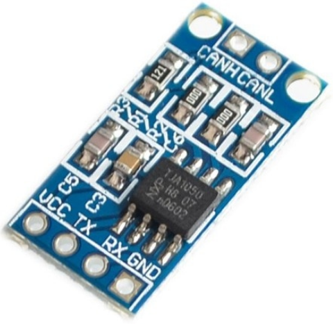
CAN transceiver
This is a NXP TJA1050 module:
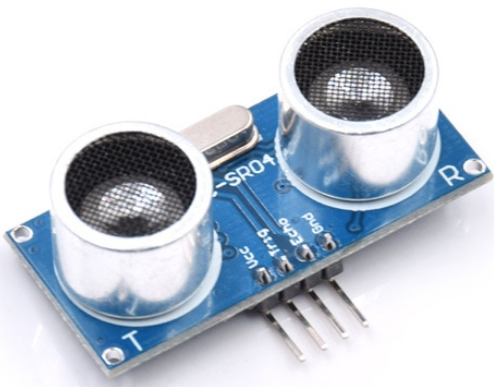
Distance sensor
This is a common ultrasonic distance sensor:
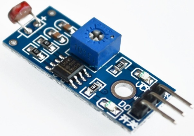
Light sensor
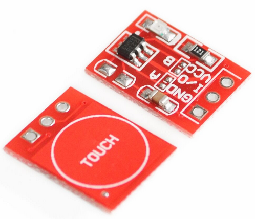
Touch sensor
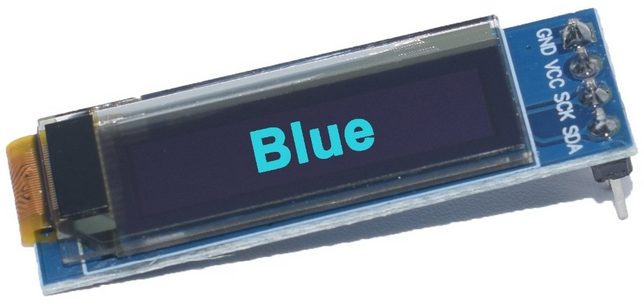
OLED screen
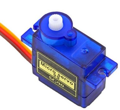
Servo motor
Designing the ECU
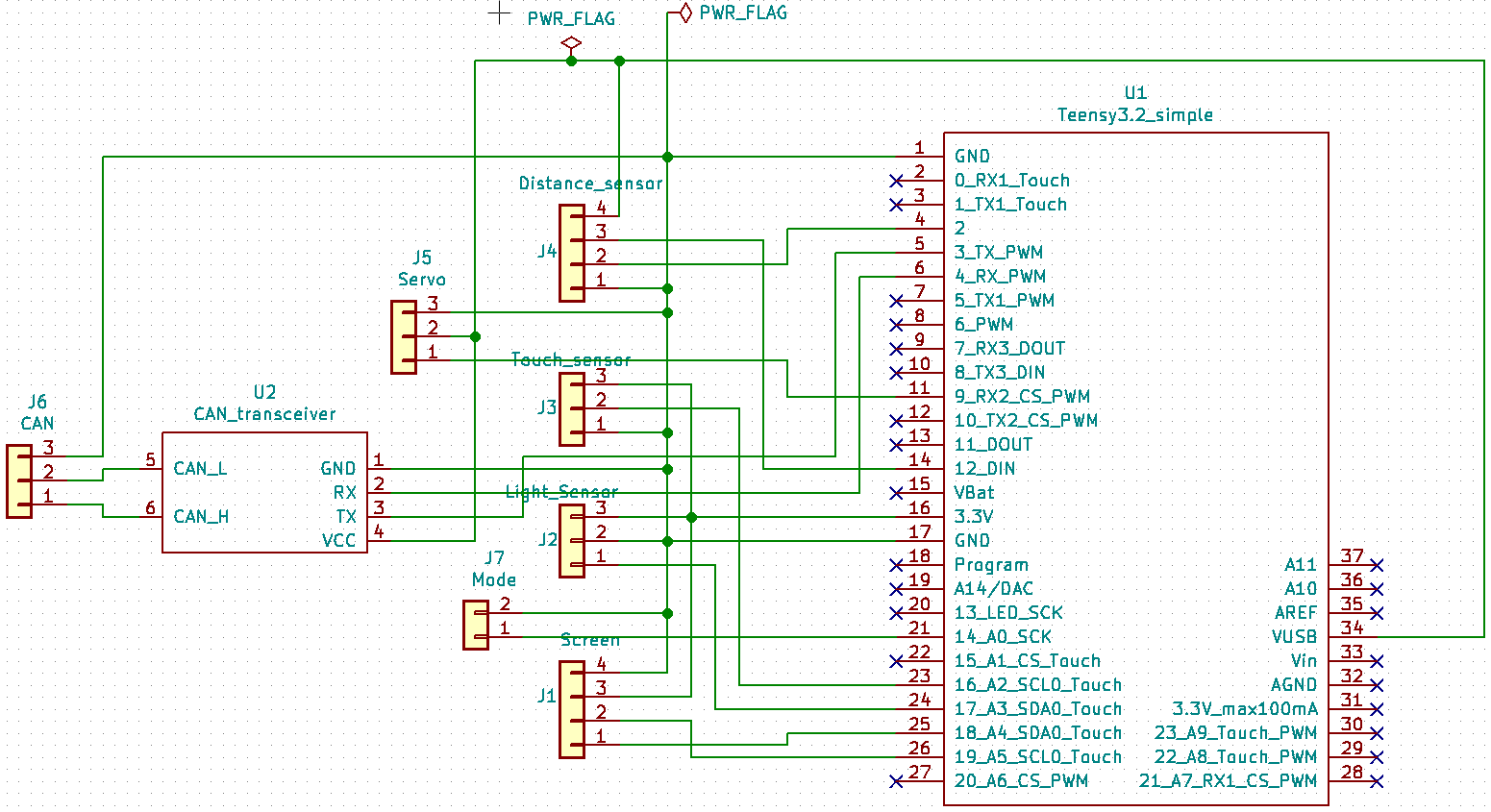
As we chose a pretty straightforward approach for designing this ECU (assembling simple modules), the electronic design in kicad was really simple.
Kicad schematics and footprints are available for the Teensy3.2 board here: https://github.com/XenGi/teensy_library.
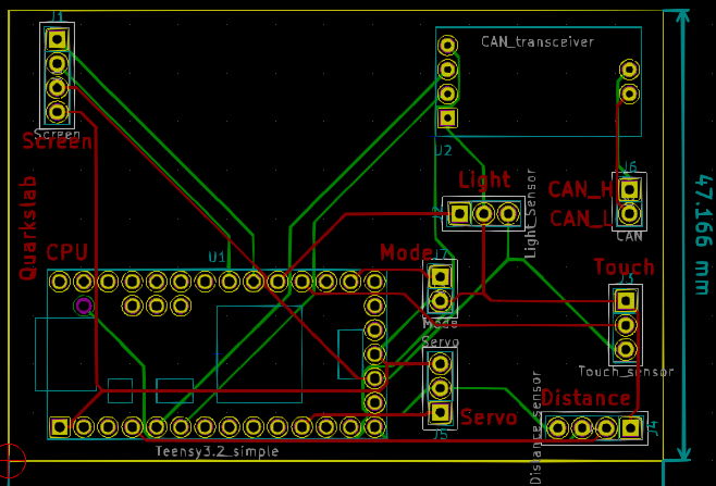
Create a new project, add a Teensy3.2 component, add simple Pin Headers for the different modules, and connect the wires:
For routing the PCB, we used the autorouter available here: https://github.com/miho/freerouting.
It can be built and run with these commands:
git clone https://github.com/miho/freerouting.git
cd freerouting
gradle wrapper
bash gradlew assemble
java -jar ./build/libs/freerouting-executable.jar
Here is the result:
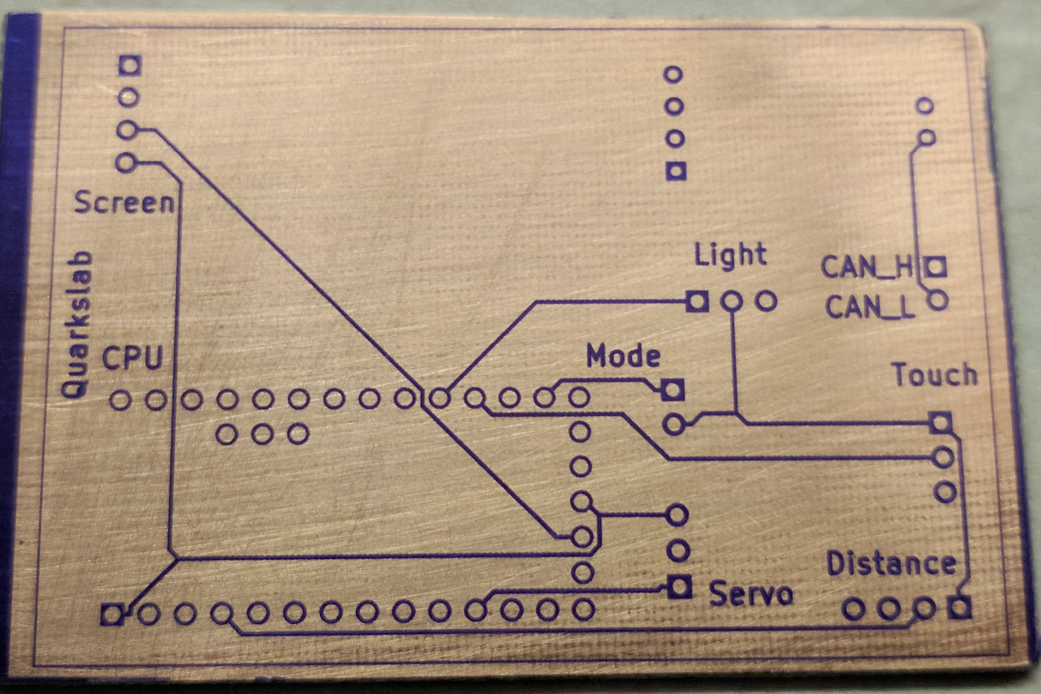
Making a prototype before outsourcing the fabrication of the PCB is generally a good idea, so we made one using a photosensitive blue film:
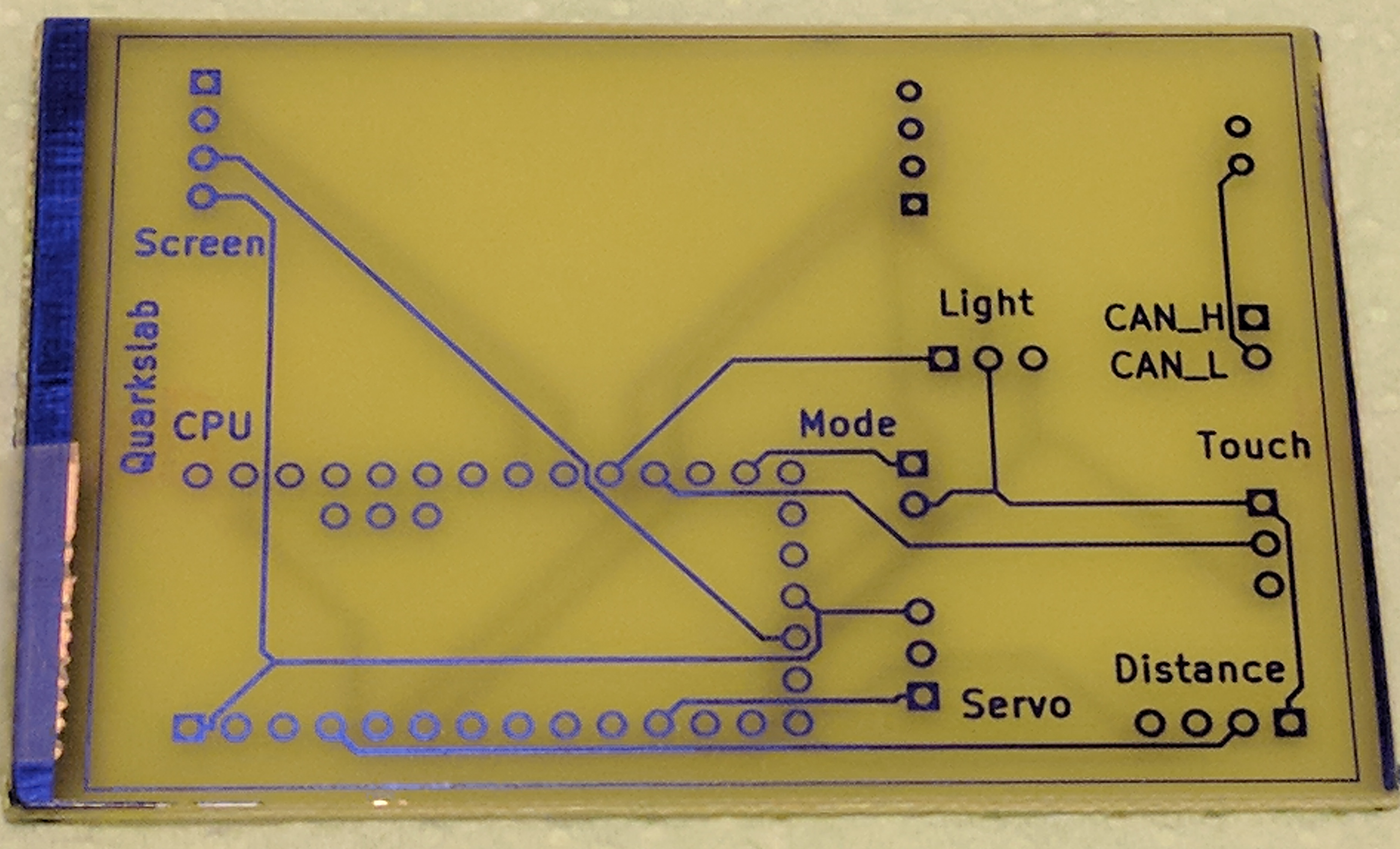
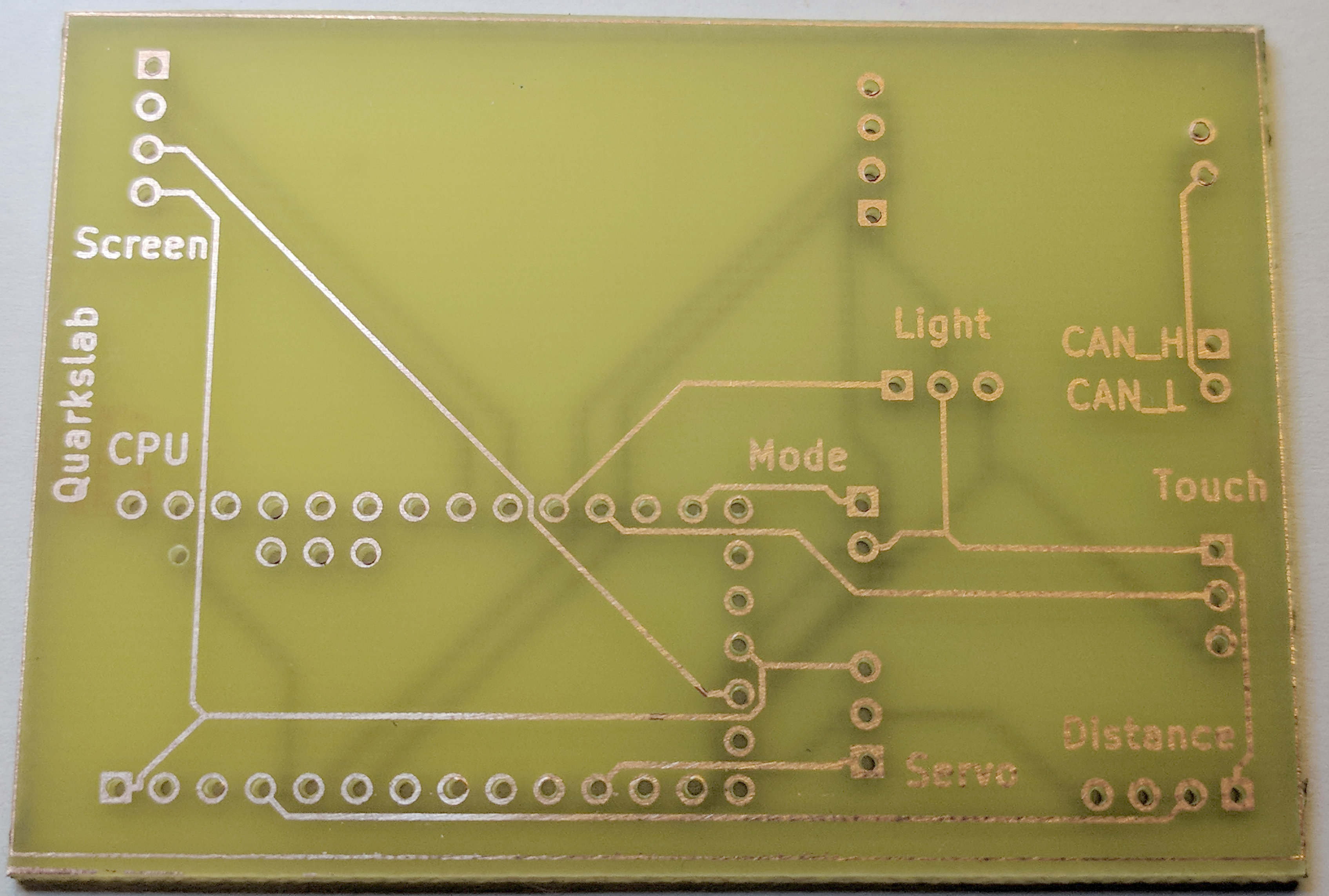
Next step, etching in ferric chloride:
Then drilling:
And soldering the modules:
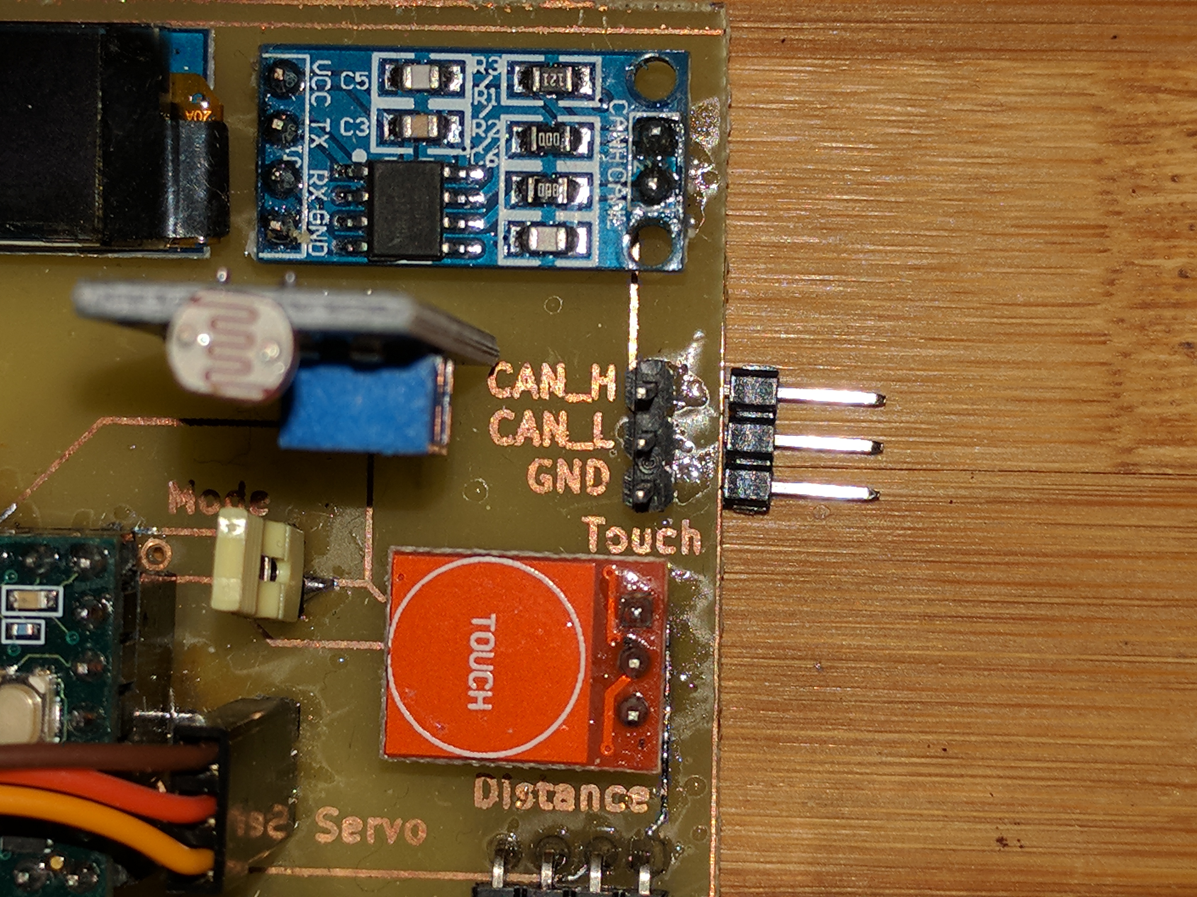
As it turned out, it was a good idea to make a prototype before ordering several PCBs, because we forgot to add a Ground pin next to the CAN bus, in order to align the ground of this ECU to another ground.
So, here is the second version:
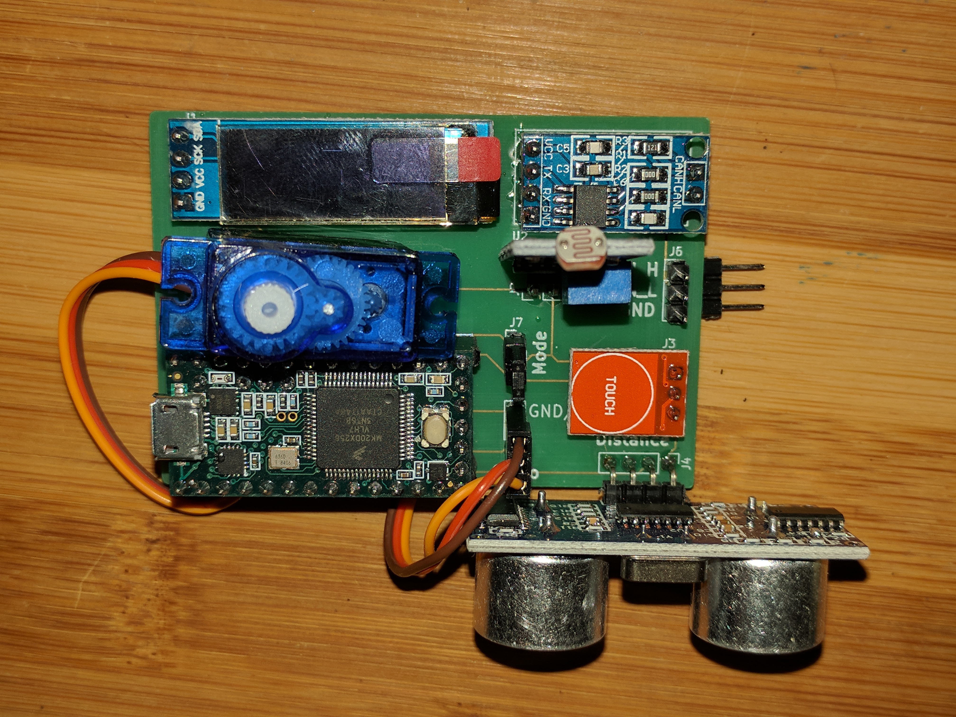
Then we ordered 25 PCBs to a PCB manufacturing company, for a clean result:
ECU software
The software to send and receive CAN messages can be very simple, basically it looks like this:
#include <FlexCAN.h>

void setup() {
  Can0.begin(500000);
}

void loop() {
  // declare a CAN message
  CAN_message_t msg = {0};

  // management of input CAN messages
  if (Can0.available()) {
    Can0.read(msg);

    // check for a specific message
    if ( (msg.id == 0x700) && (msg.len == 4) && (msg.buf[0] == 1) && (msg.buf[1] == 2) && (msg.buf[2] == 3) && (msg.buf[3] == 4) ) {

      int len = 4;            // prepare the message to send back
      msg.ext = 0;
      msg.id = 0x400;
      msg.len = len;
      for (int i = 0; i < len; i++) {
        msg.buf[i] = len-i;
      }

      Can0.write(msg);
    }
  }
  delay(1);
}
From this base, we developed several versions:
send periodic messages with different status bytes, and add basic UDS support
implement 4 logical ECUs in this hardware ECU, more UDS support
manage sensors and actuators
use a CAN database to manage the CAN messages
code clean-up: split the code in several files, documentation, etc.
All these intermediate versions have been saved as different projects and are used during the training to illustrate reverse engineering techniques, starting from very simple and ending with more realistic ECU softwares. For example, CAN databases are very often used in real-world ECUs and are a target of choice for ECU hackers. We explain how to find them and how they can be exploited.
As explained before, one major advantage of this training ECU is that it can be fuzzed, brute forced, etc. without damaging anything. The final software contains several security algorithms that can be evaluated and attacked. This is one of the main purposes of our training: illustrating on a real example several approaches to hack into an ECU, through the CAN bus or by using more hardware-oriented attacks.
In order to attack this ECU, you will need another device to communicate on the CAN bus. We use a RaspberryPi3 and a PiCAN2 shield during our training, but you can use any other hardware. One advantage of this setup is that you can script your attacks with Python, and still have a relatively good real-time communication on the CAN bus.
Open-source ECU
Due to popular demand, this project has been open-sourced. We hope it will help people look into the security of ECUs and build more robust products. You can download the whole project (Kicad and Arduino) here: https://github.com/quarkslab/training_ecu. You can buy all parts using the links provided below. We are not affiliated to any Aliexpress vendor, so feel free to buy these parts from any other web site. We just provide these links as examples, for your convenience.
Teensy3.2: The board can be purchased on many web sites, no special instruction is needed.
CAN transceiver: https://www.aliexpress.com/item/TJA1050-CAN-the-Controller-Interface-Module-the-Bus-Driver-Interface-Module/32825326387.html
Distance sensor: https://www.aliexpress.com/item/1pcs-HC-SR04-to-world-Ultrasonic-Wave-Detector-Ranging-Module-for-arduino-Distance-Sensor/32786781050.html
The PCB can be ordered in any PCB manufacturing company from the Kicad project.
In order to attack this training ECU, you will need another CAN enabled device. We recommend using a RaspberryPi3 with a PiCAN2 shield, but you can use any other setup.
To receive full support on how to use this training ECU, perform the attacks and reverse engineer the firmware, you can register to the training here https://quarkslab.com/en/trainings/practical-car-hacking/ or during the Hardwear.io conference: https://hardwear.io/.
The sessions organised at Quarkslab are customized for specific clients, whereas the sessions at Hardwear.io are planned at regular dates.
Conclusion
This simple ECU can be used for trainings, in order to make each attendee confident with CAN attacks. Its software can be customized to demonstrate different parts of the security mechanisms of a real ECU, as well as different attacks that can be performed on the CAN bus to hack into an ECU, and, for example, dump its whole memory.
We currently give the Practical Car Hacking training at Quarkslab and Hardwear.io.
Acknowledgements
Thanks to all Quarkslab colleagues who helped design this prototype and proofread this article.