Authors Stanislas Lejay, Guillaume Heilles
Category Hardware
Tags CAN, OBD, hardware, automotive, 2017
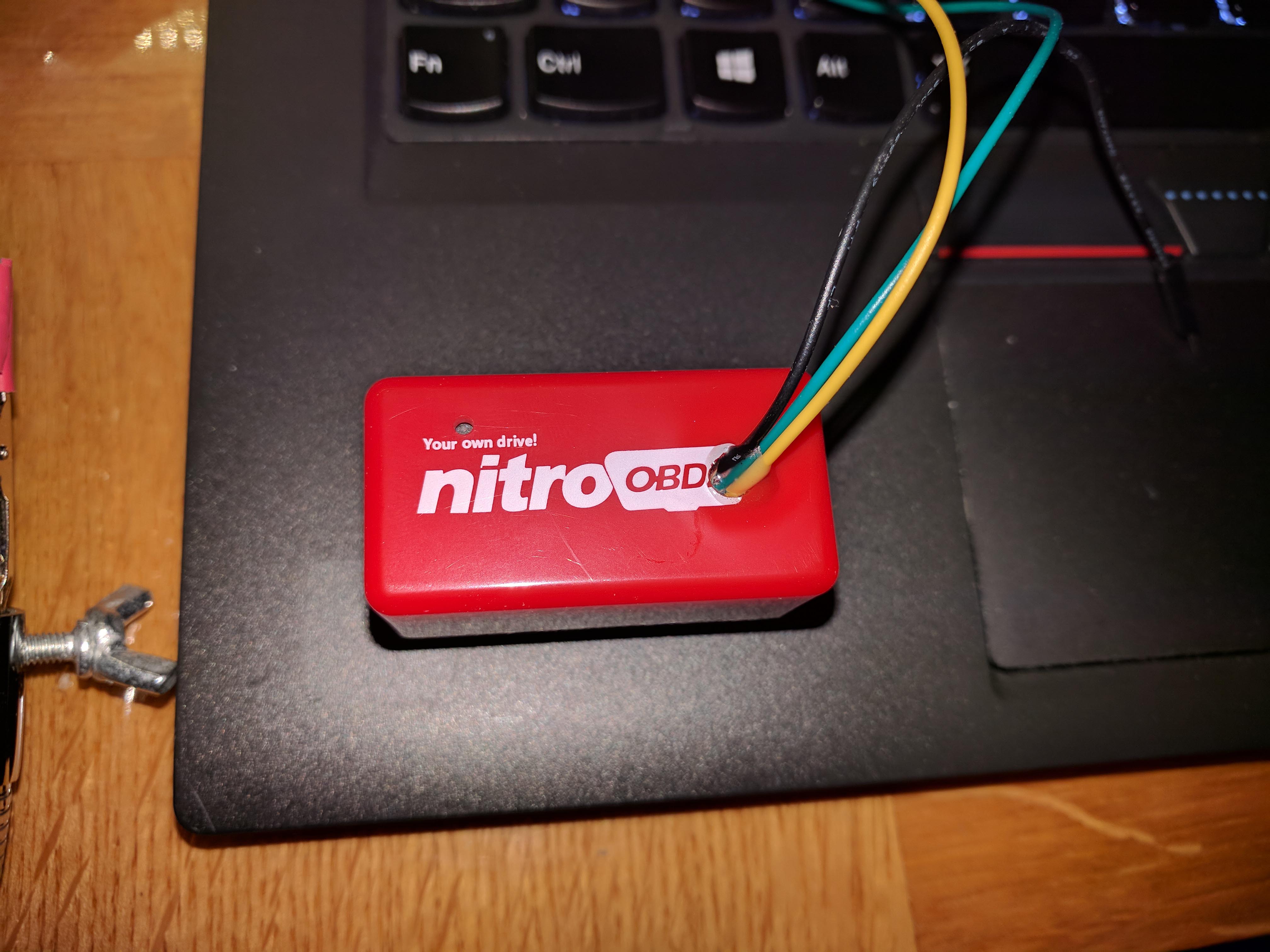
This blog post presents the reverse engineering of an OBD2 dongle called "Nitro OBD2". It is advertised like this: "NitroOBD2 is a Chip Tuning Box which can be plugged into OBD2 connector of your car to increase the performance of your car." There are a lot of testimonies on the internet about this device being a fake, while other people say that is is really working. We wanted to reverse engineer it to check by ourselves.
Context
Automotive security is a quite interesting field, and a very vast one. Attack vectors are numerous, and you can't really grasp the whole potential a car can offer. Lastly, we played a lot with it and more precisely with the https://en.wikipedia.org/wiki/CAN_bus bus, in different ways (some smarter than others). We thus began to interest ourselves in what the world has to offer in terms of CAN devices and what people do with their CAN bus.
A friend told us about a little on-board diagnostic (OBD) dongle called "Nitro OBD2", which is supposed to monitor the way you're driving and reprogram your engine according to it, in order to save fuel and/or get more power from your engine. He asked us if this thing was really working, so we bought one on http://amzn.eu/6yIOnhE, started to reverse engineer it and found a few interesting things. As we couldn’t write a full review on Amazon, we wrote this blog post instead.
PCB analysis
Before plugging this thing into a car, we decided to check what was inside.
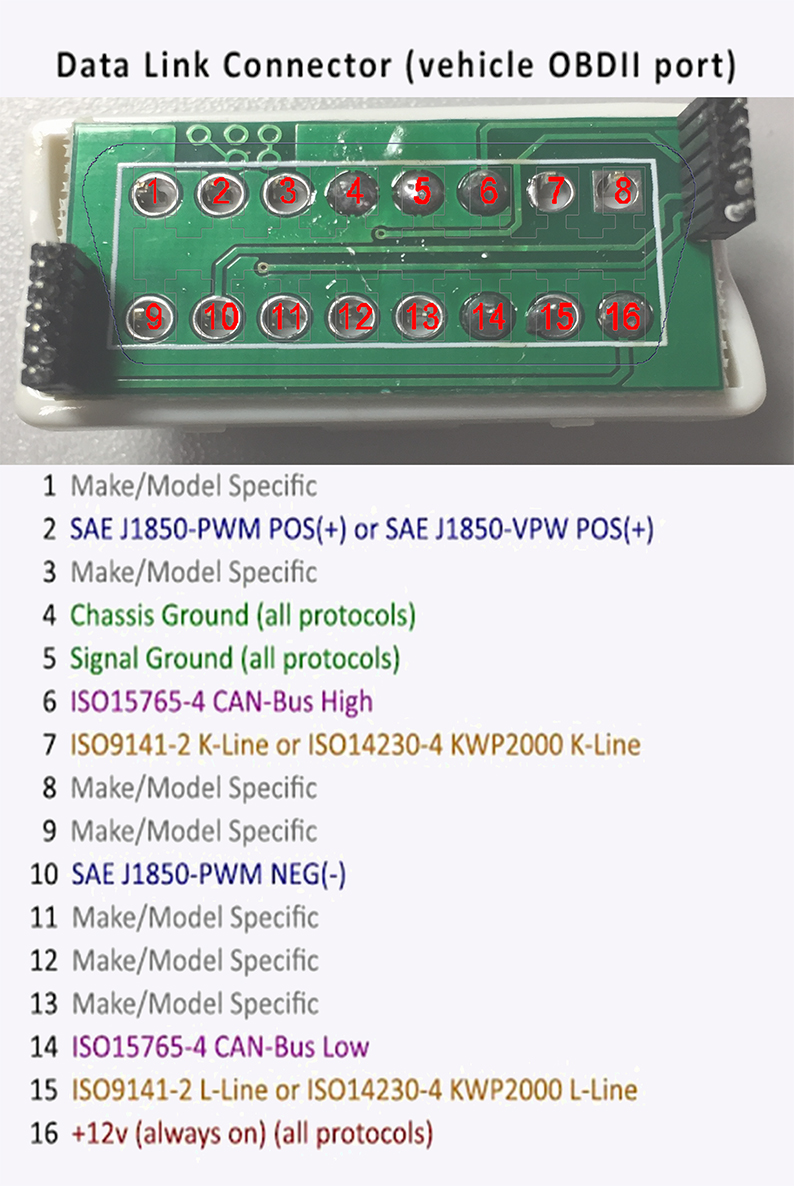
After opening the dongle, we were greeted with the classical OBD2 pinout. Here is what it looks like, and what each pin refers to:
First, we tried to figure out if the pins corresponding to CANH and CANL were at least connected (and, thankfully, they were, or else this article would have stopped here and be quite disappointing!). The connected pins were the ones corresponding to the CAN bus, J1850 bus and ISO 9141-2 protocols:
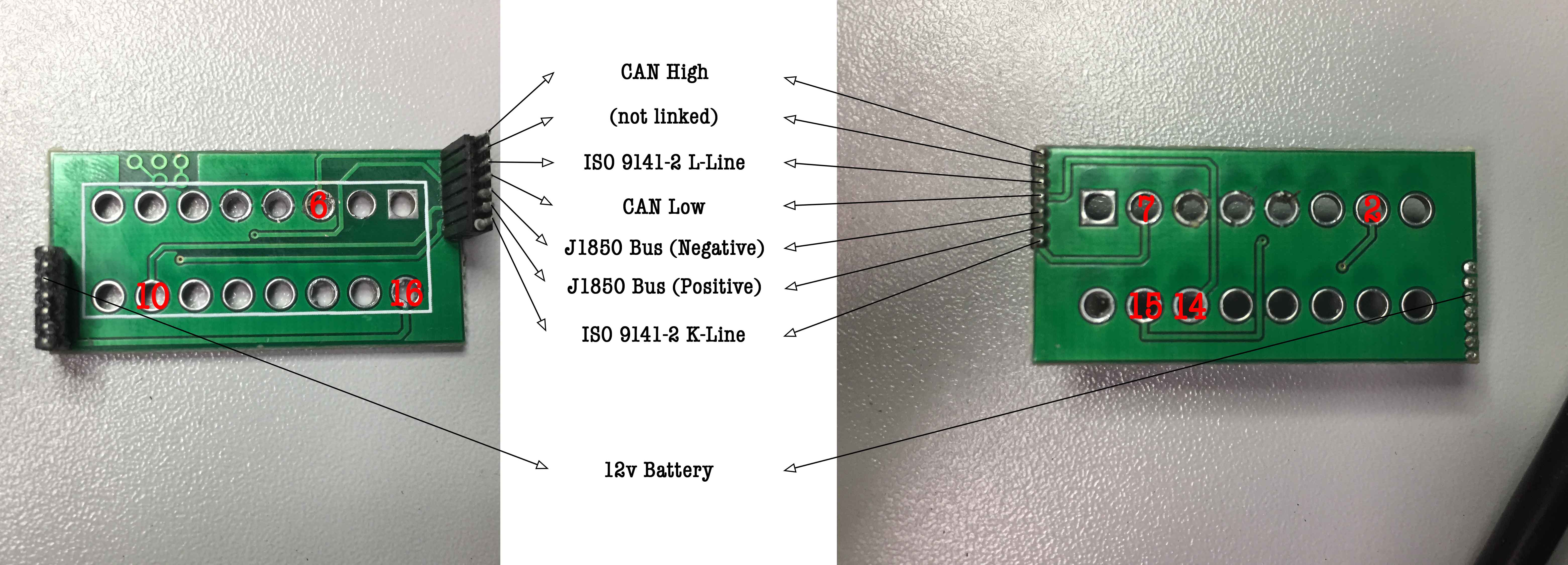
The circuit board shows that the only useful pins connected to the chip are those related to CAN, the others are connected to LEDs.
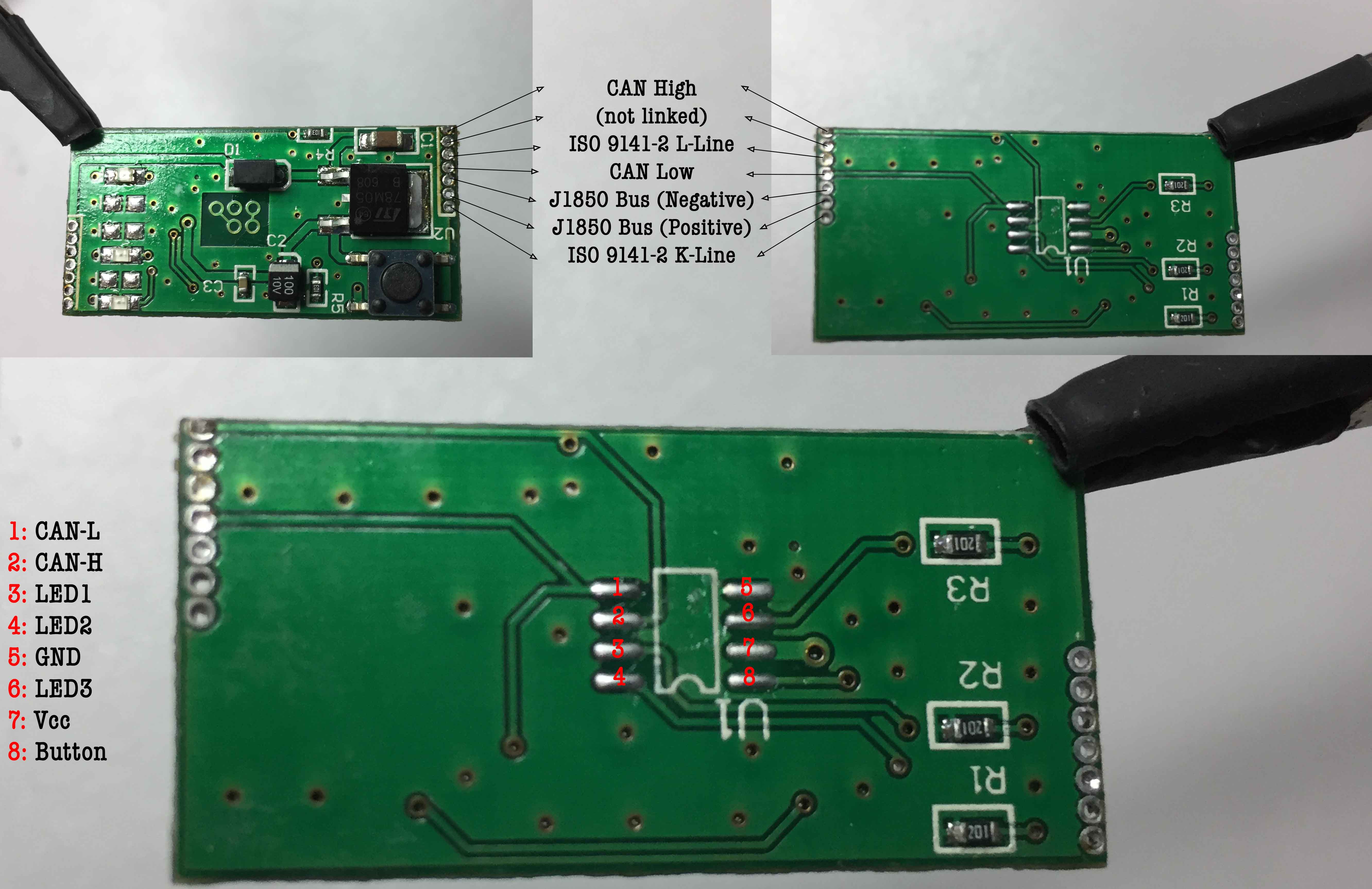
At this point, we can already recreate the basic layout of the board:
a simple power circuit
a push button
a chip
3 LEDs
The circuit board didn't seem to contain any CAN transceiver, so either there was none, either it was directly integrated in the small chip along with its software. The software part is responsible for all the magic like:
understand how the actual car works
retrieve its state
modify it
reprogram the ECUs
We began to be very sceptical about this device. Everything had to be packed into a single SOP-8 package or it was a fake.
CAN analysis
Setup
One easy way to determine if this device actually does something is to plug it on the CAN bus of a car and check if it sends anything.
We chose Guillaume's car, a 2012 diesel Suzuki Swift, because he is used to communicate with it using an ELM327 and Torque on Android. It works pretty well to get various information about the engine, and reset the error codes (DTCs).
In order to see if the Nitro OBD2 is actually doing something on the CAN bus, we just need to record all CAN messages, before and after plugging it, and check if new messages are sent by the Nitro OBD2. So we first recorded all CAN messages seen on the OBD port, using a RaspberryPi and a PiCAN2 shield, and Stan's port of https://github.com/P1kachu/python-socketcan-monitor which enables to read from socket-can interfaces.
The following setup is used to record the CAN messages directly from the OBD2 port:
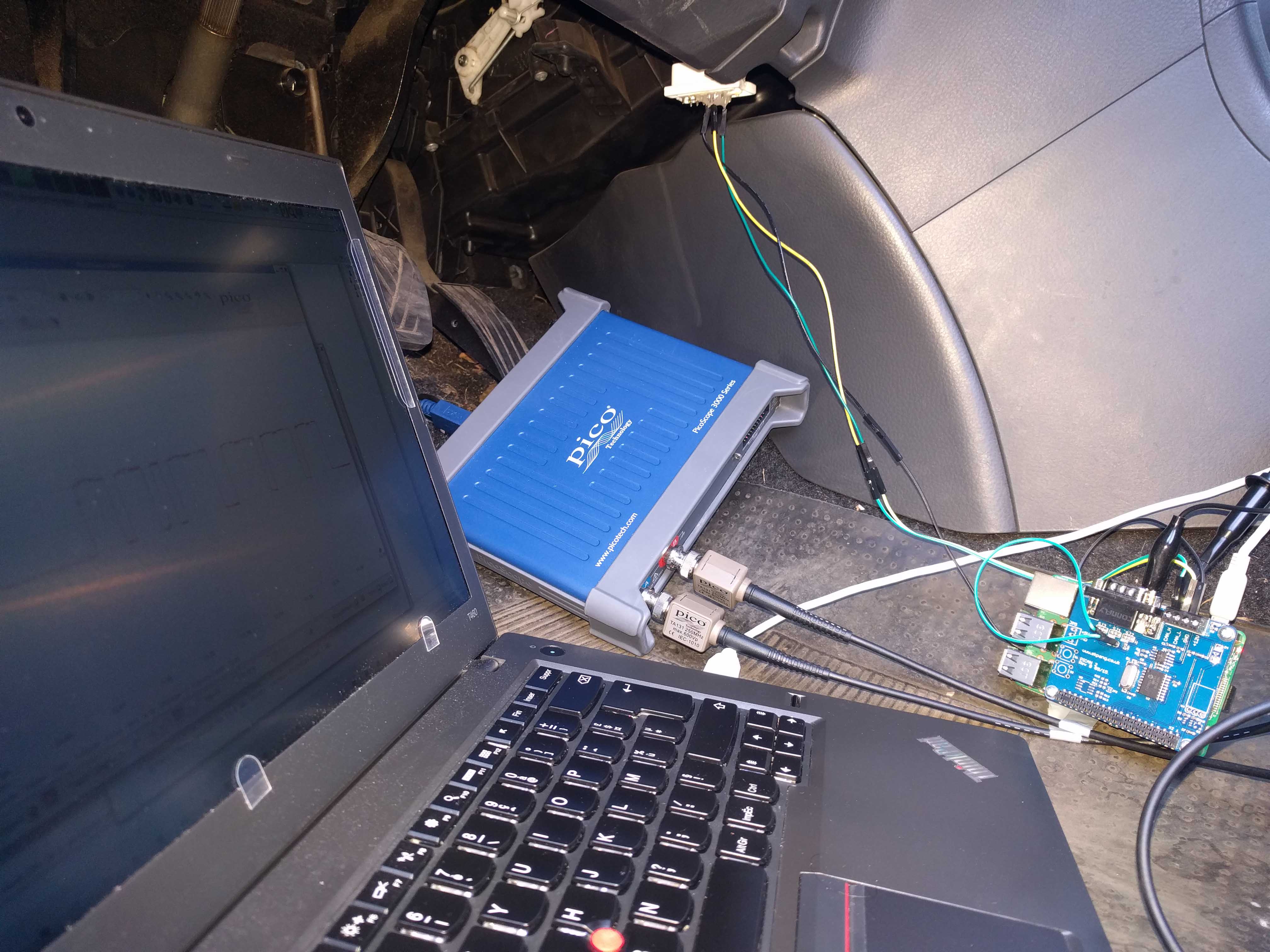
Just to be sure, we also checked the CAN signals with a PicoScope. As expected, we can see the CAN_H and CAN_L signals.
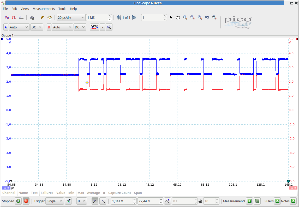
We have an operational setup with a CAN bus working as expected and some monitoring tools.
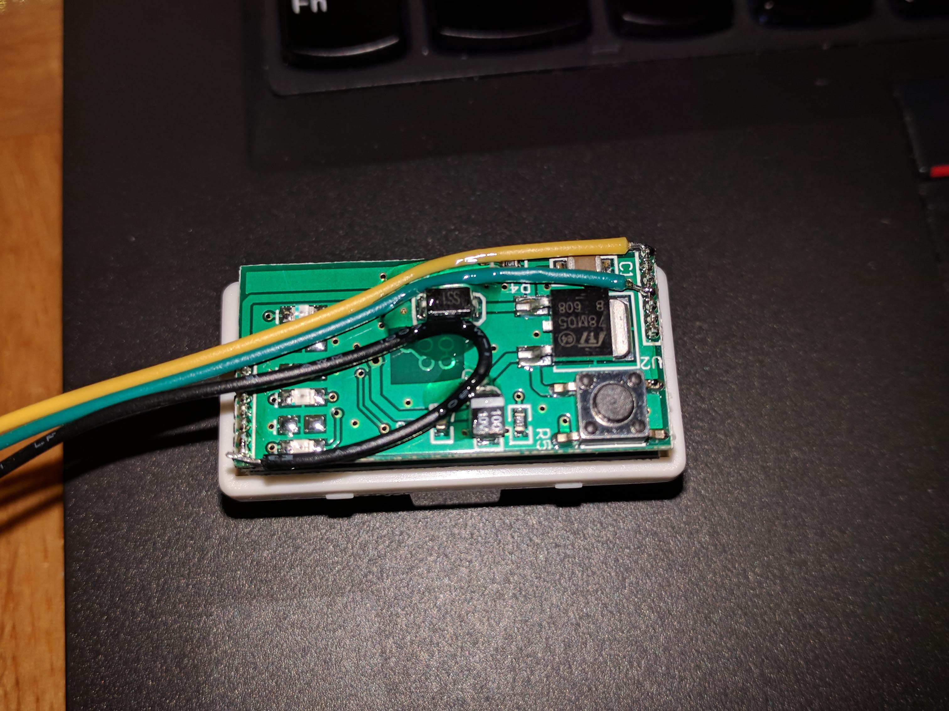
Next, we need to record the CAN messages when the Nitro device is plugged in. As there is only one OBD2 port in the car, we decided to connect our monitoring tool inside the Nitro device.
So we opened the Nitro OBD2 to solder 3 wires on the Ground, CAN_High and CAN_Low and plugged the Raspberry's PiCAN2 interface on these wires.
With this setup, we are able to sniff the CAN bus traffic, while the Nitro OBD2 is plugged in the car.
Results
The CAN bus traffic without the Nitro OBD2 plugged in is shown below:

And here is the CAN bus traffic with the Nitro OBD2 plugged in:
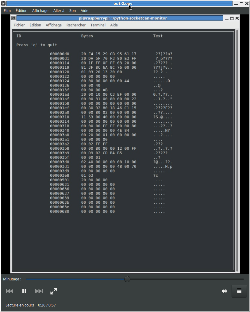
A quick comparison between the two images shows that there is no new message recorded while the Nitro OBD2 is plugged in.
So this chip is not really communicating on the CAN bus. It just observes passively the CAN_H and CAN_L signals to check for CAN activity and blink the LEDs.
Chip analysis
From that point on, we can already say that this chip is not communicating on the CAN bus, which makes sense since we could not find any CAN transceiver on the board. Sadly enough, there is no engraving on the single chip of this device so we could not just check its datasheet. But as we are curious and like to decap chips, we also wanted to check the inside of the chip. After a quick bath in sulfuric acid at 200°C, here is a picture of the Nitro OBD2 chip:
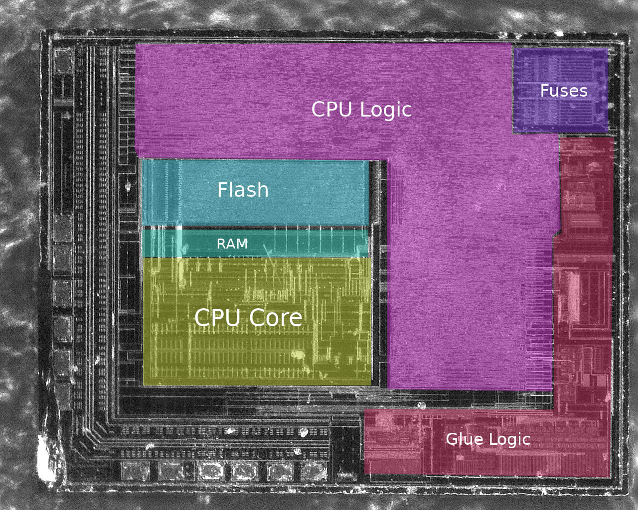
In this picture, we can see the RAM, Flash and CPU core, but very few other things. This looks like a standard microcontroller, with no special embedded device. Is it possible that the designers of this chip could stuff a CAN transceiver inside it?
For reference, here is one of the most common CAN transceivers on the left, the TJA1050, also decapped, side to side with the Nitro's chip:
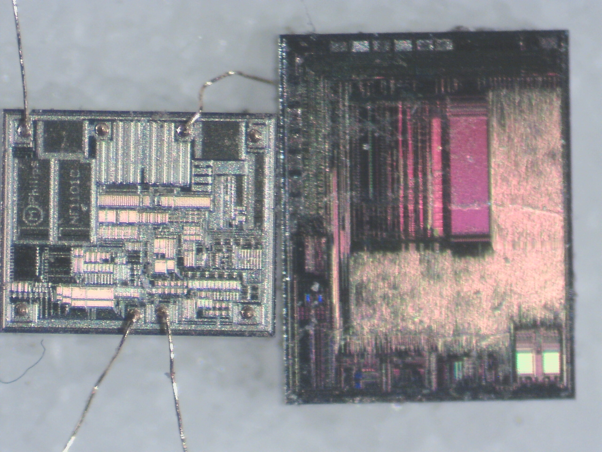
As you can see, the design of the CAN transceiver is very different from the Nitro OBD2's chip. Moreover, there is no room in the Nitro OBD2's chip for anything of this size. This confirms the hypothesis that the Nitro OBD's chip does not embed any CAN transceiver, and is unable to communicate on the CAN bus.
The Devil's Advocate
Following all these different steps, we were confident that this tool was not doing anything apart from blinking LEDs. But people might still be sceptical about this conclusion, so we tried to find some ways to challenge it. Here are some statements/assumptions we made to harden it:
Some people say you have to wait ~200 km for it to be effective, so how can we say for sure that it's useless when we only drove 15 km looking at the CAN monitor? Plugging the tool in the car doesn't raise any new arbitration ID, which means either:
It uses an arbitration ID already used by our test car, so it sends messages as a living ECU in the car, which looks like a pretty bad idea because that would mess up with the ECU's communication.
It doesn't query anything, and relies on the broadcasted messages only. This second option would require the tool to know every CAN system on any car to understand what each message means. This seems even more stupid than querying standard OBD2 PIDs that would at least give a slight idea of the driver's driving habits (like, how much the accelerator is depressed, the average speed/RPM, etc).
Anyway, for sure, there is no CAN transceiver on this device...
So yes, we are pretty confident in our analysis and are thus able to offer the following conclusion.
Conclusion
As a guy said in his Amazon comment: "Save 10 bucks, buy some fuel instead."