Author Julien Rakotomalala
Category Hardware
Tags hardware, automotive, embedded-device, 2024
In this article, we'll see how to put an entire car into a transportable box from scratch or at least the main electronic components.
Introduction
That is not new anymore; cars are becoming smarter. They are full of sensors gathering information for various purposes, connected to the ECU (Electronic Control Unit) that computes inputs and, ultimately, acts on actuators. This system has existed for years, and the number of domains to which it applies is expanding day by day.
We will present the VAGBox, as I like to call it, where VAG stands for Volkswagen Aktien Gesellschaft which means "joint-stock company", and it is the parent company that sells passenger cars under the Audi, Bentley, Bugatti, Cupra, Jetta, Lamborghini, Porsche, SEAT, Škoda and Volkswagen brands.
The VAGBox is not the first 'car in a box' made by Quarkslab. Indeed, in 2022, Philippe Azalbert released a very comprehensive version based on a 2017 Ford C-Max. You can watch a French interview he conducted here. Additionally, other companies, like Digiteq Automotive, also construct cars in boxes, although their primary purpose is more aligned with test benches rather than demonstrations and education.
There are several communication protocols specific to cars, such as CAN, Flex Ray, and automotive Ethernet. The reasons for building another one are twofold. Firstly, it is to diversify the range of car models we have. Even though car manufacturers are more like integrators nowadays, they all have specific softwares and implementations. Secondly, Quarkslab offers a Practical Car Hacking training, and due to the challenges of bringing an entire car or the lack of available space, we find it more efficient to extract relevant parts of a car and place them in a transportable wheel box. This approach also prevents students from accidentally damaging a real car. The last reason is to use these setups for demonstrations at various shows in which Quarkslab participates.
The VAGBox is oriented towards connectivity and is lightweight. By that, I mean, I included the most important ECUs that compose a basic car, such as the gateway and the body control module. Additionally, I incorporated those ECUs related to external connectivity, including Bluetooth, Wi-Fi, and 2G/3G/4G, such as the In-Vehicle Infotainment (IVI), and the e-CALL or Telematic Control Unit (TCU). Unlike the first Car in a Box, there are no actuators in this setup.
Now that the introduction is done, let's see how to do it!
Buying
Which and why
The VAGBox is made from a 2016 Volkswagen Passat B8. It is based on the platform MQB which is a shared modular design construction. Cars such as the Audi A3 MK3, the VW Golf MK7, the Škoda Octavia Mk3 or the SEAT León Mk3 not only share the same platform but also utilize the same ECUs, making them very common.
The initial step was to list the ECUs and the components to include in the box. It determined the size of the box. For the VAGBox, the objective was to use the smallest and most practical box possible. I wanted it in a plug-and-play style, requiring no setup other than turning it on.
As mentioned in the introduction, our aim was simplicity. Typically, the first ECU to include is the instrument cluster (ICM) due to its role and the wealth of visual information it provides to the user about the car.
The second ECU is, of course, the Body Control Module (BCM), responsible for various functions such as locking/unlocking doors, controlling interior and exterior lights, waking up other ECUs, and more.
The third ECU is the infotainment unit, for two reasons:
- It is the ECU with the highest level of user interactivity, storing users' data, pairing with smartphones, and connecting to other ECUs through the CAN bus or automotive Ethernet. During presentations, it adds visual content.
- It is a possible and interesting entry point for an attacker. IVI has Bluetooth, USB ports and sometimes Wi-Fi. It usually uses traditional operating systems like Windows CE, Android or QNX, making them an interesting target for workshops.
The fourth ECU is the eCALL, which, in most cases, provides the vehicle access to the outside using eSIM for receiving updates and more. It is also capable of emitting emergency calls and sending data when an accident is detected.
The fifth ECU is the gateway, acting as a firewall transferring data across internal networks and providing physical isolation between different CAN bus. Typically, the eCALL is not connected to the same network as the engine control unit (ECU), although some specific data may be exchanged between them.
Finally, the KESSY (Keyless Entry Start SYstem) module, used for the passive key entry feature (PKE) and for starting the vehicle without the need to physically use the key.
In my opinion, these ECUs represent the minimum required for a complete, lightweight car in a box.
ECUs
There are three ways to get ECUs:
- From manufacturers: this solution is the most expensive and ECUs need to be manually calibrated with OEM tools that we do not have.
- From a scrapyard: the advantages include direct access to a vehicle, wiring harnesses, and connectors, as well as the possibility to check if ECU(s) are working properly. The inconveniences include finding the correct vehicle, and most of the time, you have to dismantle everything yourself.
- From the Internet: this method offers the benefit of choosing from a wide range of vehicles. On some websites like "ovoko.com", parts are grouped by vehicles, allowing you to obtain ECUs from the same one. However, ECUs are secondhand, and most of the time, they come from accident-damaged cars. There is neither a guarantee to receive a working ECU nor the matching connector.
The VAGBox is built with ECUs ordered from ovoko's website and from two different cars, which will create some issues that I'll speak about later.
Accessories
The VAGBox is, of course, also composed of side components. There is not much to say about them, so here is a bullet list of what I bought:
- AC 110/220v to DC 12v transformer (easily findable on the Internet)
- 3-meter-long power cord
- DB9 ports (to easily connect to CAN buses)
- 10 mm plywood panel for the box frame
- A complete Wiring harness from a 2016 Volkswagen Passat B8
- Braided cable sleeve and electrical tape (for custom wiring harness)
- Bungee cord to maintain ECUs in place
Box
Then came the time to find a box that fits every ECU and accessory. It must meet the following criteria:
- As small as possible
- Equipped with wheels and a trolley
- Very strong (previous experiences show that transportation, especially by plane, is very critical)
- The lid must be able to stay open
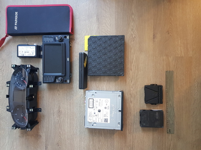
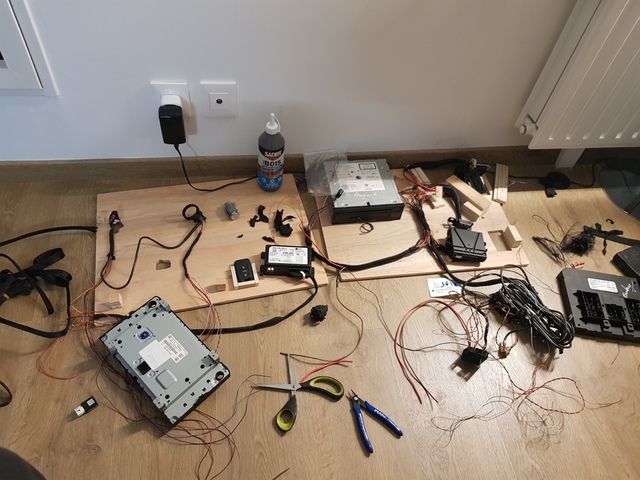
At the moment of choosing, I had already ordered and received ECUs, so I took measurements by placing components on the floor, following some criteria (again). The Instrument Cluster (IC) and In-Vehicle Infotainment (IVI) screen must be placed on the lid, which is the most visible place on the box. Besides, I wanted to hide the ECUs' connectors as much as possible.
Here is a picture of what was supposed to be the final positioning:
Now that I knew the minimum required size for the box, and with the list of criteria in mind, a quick research on the Internet led me to this one:
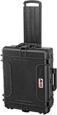
The inside dimensions of the box are 538 mm wide, 405 mm long, and 190 mm high, and it comes with protective foam. At first glance, the box seemed too small but it was not.
Building
Main panels
The box is made of strong plastic material, but it cannot directly support the components. Therefore, I've devised a solution with a separate panel for each inner side of the box. These panels are glued and used to affix each component on them. So I took some measurements and cut wood panels, which is quite easy when using the proper tools (as always).
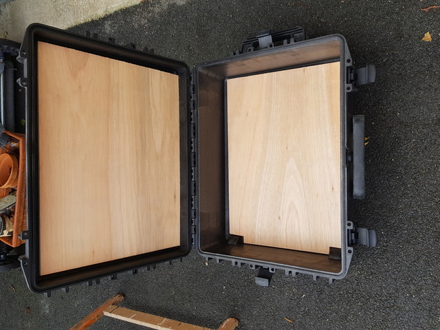
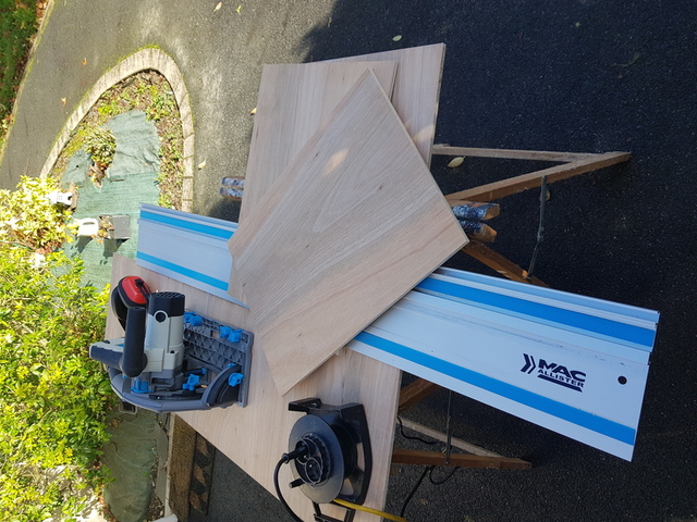
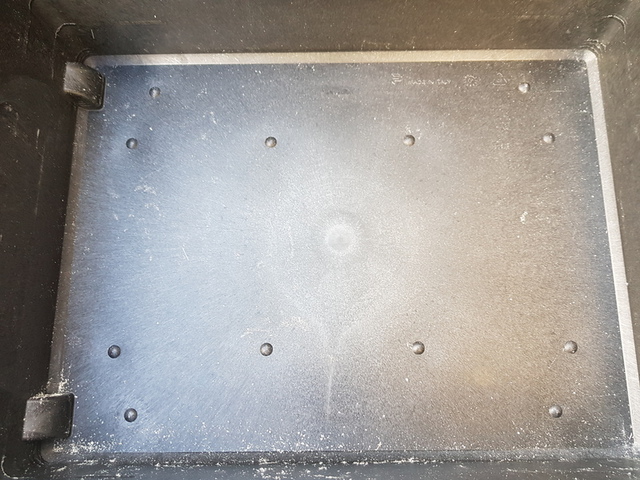
On the lower side of the box, the surface wasn't perfectly flat; some 2 mm high humps prevented proper gluing of the panel. To fix this, I used a router to thin spots on the wood panel.
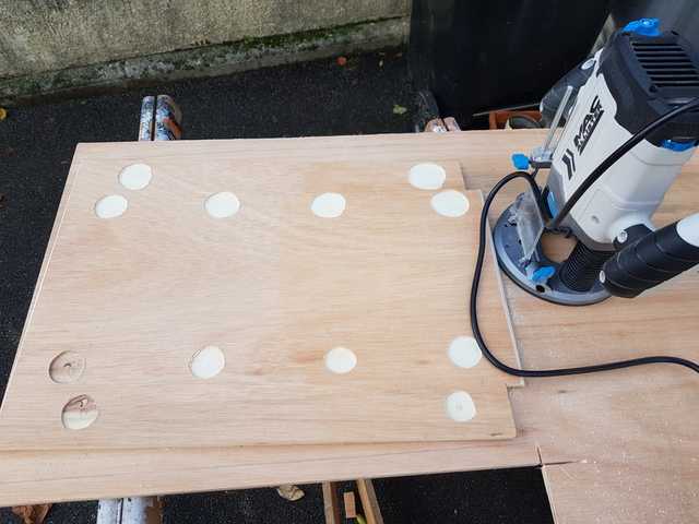
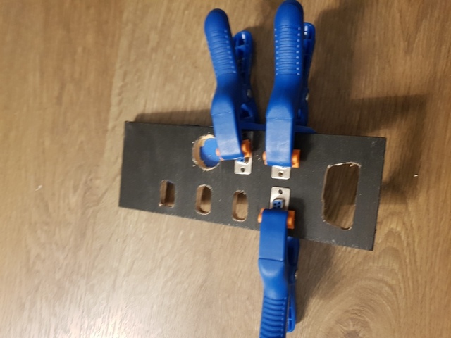
As the height of the box is limited (cf. box's criteria) and to maximize the available height space between panels when the box is closed, I drilled holes in the plywood panels at the spots corresponding to the ECUs' connectors, like this:
Without this gained space, about 10 mm depth, the VAGBox would not be able to close properly.
ECUs' stand
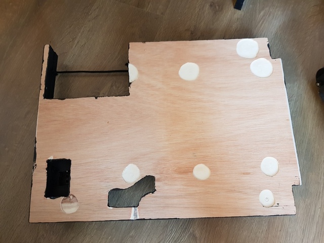
Now that I had the panels and knew where to fit ECUs, it was time to think of how to fix them. While I could have placed them on their flat side, I wanted the connectors to be hidden. A straightforward solution was to create stands by cutting, stacking, and gluing as many plywood pieces together as needed to achieve the required depth. I then glued them onto the wood panel using wood glue.
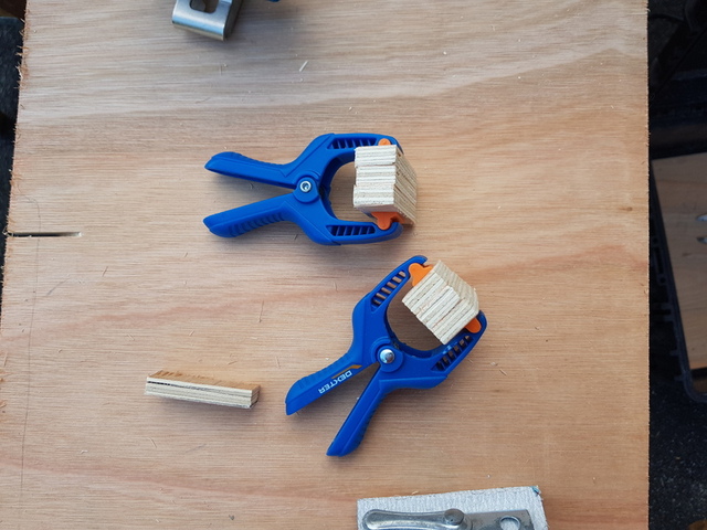
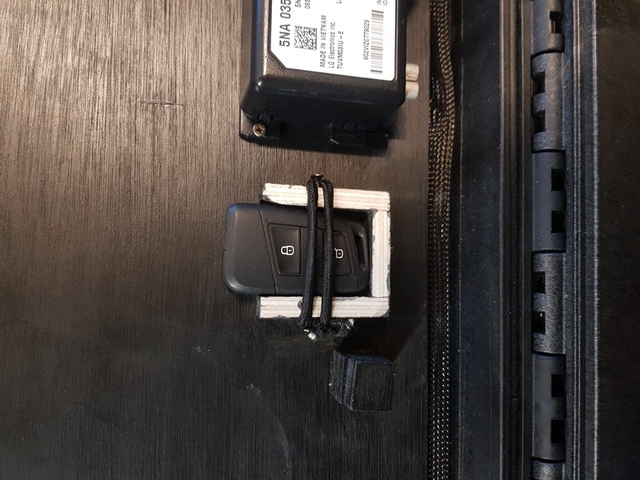
For the upper panel, I secured the IC and IVI screen with screws, ensuring that the length of the screws approximately matches the total depth of the support plus the panel for a secure and strong fixation. The eCALL is directly fixed to the panel and for the key fob, I also made a sort of stand, still using plywood that I glued on the panel. Finally, I secured it using a bungee cord.
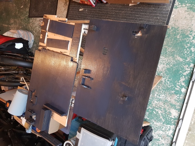
I also crafted stands for each ECU on the lower panel and secured them using the same method as for the key fob. The power supply is directly screwed, and the IVI will be secured using an aluminium plate directly fixed onto the plywood panel.
Finally, the entire panels have been painted in black for a better finish.
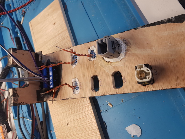
Control panel
The control panel is placed between IVI and BCM and is composed of:
- 5 female DB9 connectors, each connected to a CAN bus, providing easy access to different networks, bypassing gateway restrictions
- 1 OBD2 port connected to power and the CAN bus "diag" to include regular diagnostic access to ECUs
- 1 Start/Stop button directly connected to the KESSY module which initiates the immobilizer check procedure
- 1 USB port connected to the radio
Regarding the construction, I positioned the different pieces I wanted on the upper plate and traced their outlines. Then, I drilled holes and used the router. Finally, I glued the components.
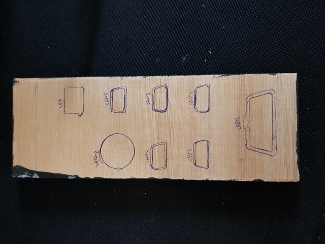
I would not be honest if I said that I did it perfectly on the first attempt. I drilled too far to the left for the USB space, so it ended up right above the vertical plywood structure of the panel.
Two options:
- Use the router to thin down the vertical plywood piece
- Widen the existing hole to the right and fill the left side again with wood filler (I chose this one)
Finally, I left some free space in case I would like to add additional components (e.g. a kill switch).
Wiring harness
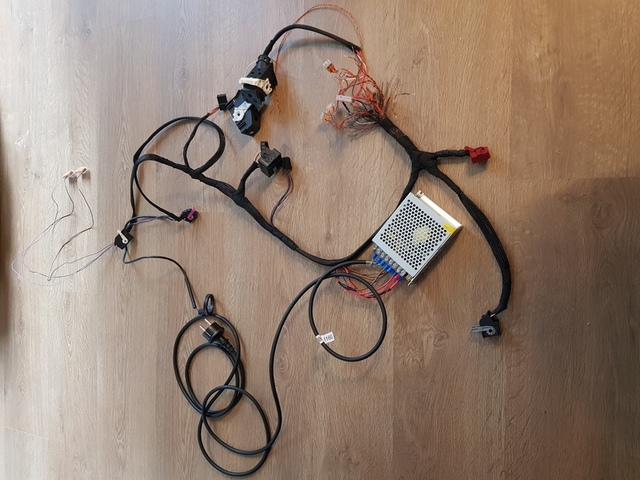
I must have spent most of this project time crafting this lite wiring harness from the original one. First of all, here is the size of the OEM:
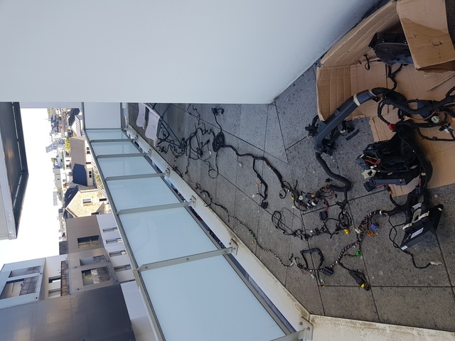
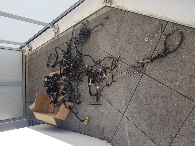
I could have made it from scratch, relying solely on OEM documentation, but I didn't have wires or the connectors at home (which I really wanted to obtain). Besides I found one for about 75€ whereas others are sold for 150-200€. A good deal for me, but as I mentioned before, it also involves a lot of work (a couple of hours). At least now, I have enough cables to build like 3 or 4 other cars in a box, so this is nice.
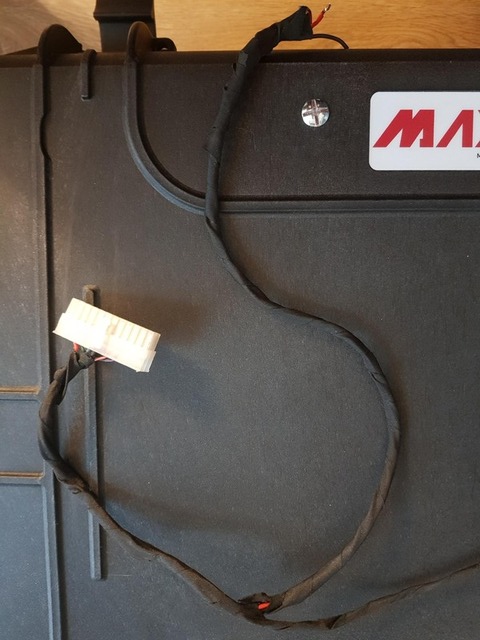
To make the wiring harness discreet and clean from the outside, I decided to use a braided cable sleeve and electrical tape. Here is the result:
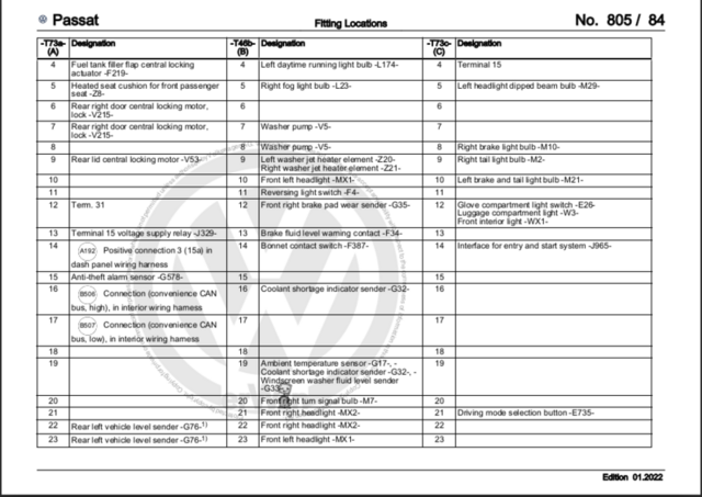
It was not a very difficult job, but I had to think about cable lengths. Most of the ECUs' connectors have fewer than 32 pins and they are not all used. However, for the BCM, the one that manages a lot of input/output in the car, there are at least 60.
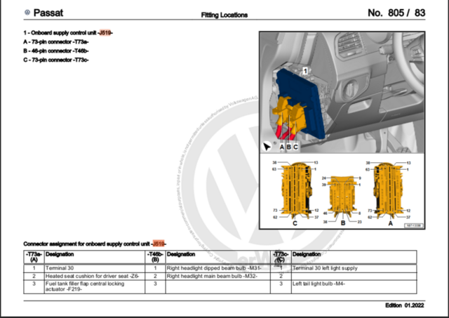
Here is a picture and an extract from the OEM documentation.
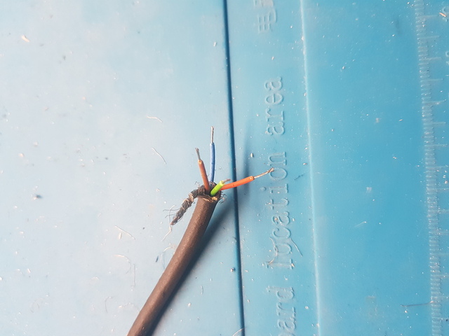
While cutting wires on the original harness, I found this on the BCM connectors:
Obviously, it is not part of the original wiring harness. That means someone customized his/her car with an additional module, connected to power, the infotainment CAN bus, the hazard warning light switch, and the rear right door contact switch. I still wonder what thing was connected to it.
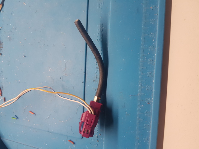
The IVI screen and the female USB connector use high-speed data cable (HSD). These are used in the context of automotive communication systems and are shielded to protect signals from electromagnetic interference that may be present in the automotive environment. Of course, I needed to shorten them because the distance between the two components is much smaller in the VAGBox than in the car. I thought it was going to be tricky but in the end, it was pretty easy, using a third hand.
You may have noticed that I mentioned the "manufacturer data sheet" twice; it is a must-have! Basically, it contains everything about the ECUs, their location, pinout, parts number, and it also provides network diagrams. You can find parts of it on forums or you can buy an access token for an hour to one year and browse the official manufacturer's mechanic website. It does not cost a lot and it's a time-saving measure for sure.
Powering the box
As the box is used for international trainings and shows, it requires a transformer from 110/220V to 12V.
Historically, DC 6V and 12V have been used in cars. Over time, the 12V system became more popular due to its advantages in terms of power delivery and component design. Higher-voltage systems would require thicker and heavier wiring to handle the same power. Also, 12V system is considered safer for automotive applications, as it reduces the risk of serious injury in the event of accidental contact. Besides, lead-acid batteries are well suited for 12V systems.
Therefore, a transformer from AC 110/220V to DC 12V is required. The only requirements were for it to be as small as possible with a minimum of 5A to correctly power each ECU. The choice was quite straightforward, and it was ordered on A***** (once again).
Lastly, I added a 3-meter-long power cord to ensure there was enough length to reach a power plug.
Packing altogether & final result (v1)
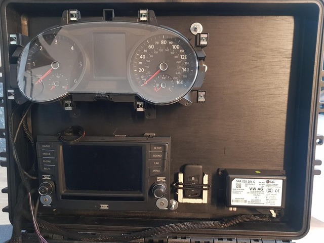
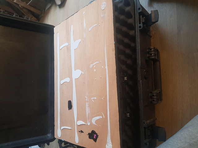
Now that the parts are ready, it's time to assemble them to build the VAGBox. The first thing I did was to glue the main panels to the box with a multi-material adhesive, and I waited about 24 hours for it to dry.
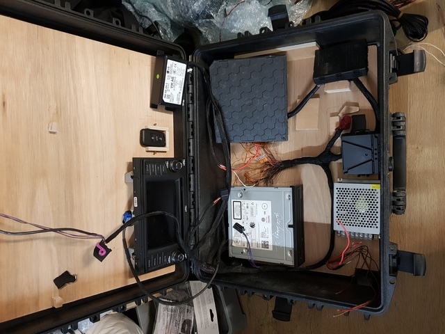
I fixed each component as described earlier, powered on the box, and here is the result:
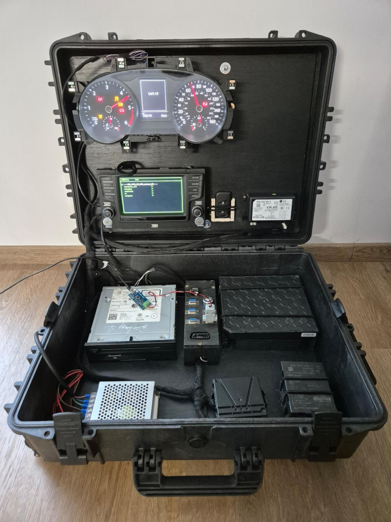
You may have noticed that I left an empty space on the right side of the upper panel. This is because I'd like to add a second control panel with buttons to control things such as the gas gauge, the speed needle, the RPM needle, lights, and so on. This is something I'll do later.
Instrument cluster demo mode
As mentioned earlier, the instrument cluster receives and displays a lot of information from ECUs to the driver. Remember, one of the VAGBox's purposes is for demonstrations, and this is the kind of place where visual elements attract people. So, what better ECU than the IC for this task? The thing is I don't have any VAG car fitting the MQB platform to capture frames sent to the IC. Well, I have a VW transporter at my disposal with nearly the same IC, but it is different, and so are the CAN arbitration IDs. And, I realized it after spending an entire day trying to get access to the "Convenience" CAN bus using basic piercing probes I bought the same morning. I ended up making incisions using crocodile clips. (Today, I use the Fluke TP81 probes which are awesome!)
I could have tried to generate such traffic manually, but it would have required too much time.
While searching for ideas on the Internet, I found a Github project by "r00li" called CarCluster capable of "controlling car instrument clusters from a computer for gaming using an ESP32" and an MCP2515 CAN bus module. In addition, it provides a web interface that contains buttons and range sliders.
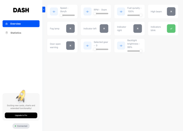
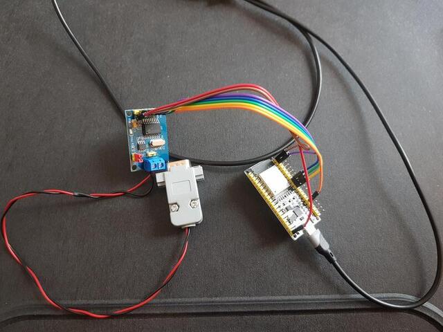
The module can be interfaced with the software SimHub "a modular multi sim dashboard and tactile feedback software".
From here, the idea was simple: get familiar with CarCluster and SimHub, then find a compatible car game (Dirt 3) and capture sent CAN frames while playing using the Quarkslab CAN adapter made by Philippe Azalbert. As the video game did not send information about coolant temperature, I injected periodic frames in the capture. Here is the final result:
For this to work and be replayed, the BCM must be powered off or disconnected. Otherwise, as it's in idle state, it won't let the IC wake up. Why? Because the BCM is the main ECU. It is the one that receives RF signals from the key fob for locking/unlocking the car. It is the one that sends CAN frames to wake up other ECUs and many other things that are not the topic of this blog. So when a wake-up frame is sent but not from the BCM, it catches it and immediately sends an 'idle' CAN frame, leading to an ECU waking up and going idle 10 times per second.
Issues
Of course, everything did not work on the first attempt, and some things still do not work for some reason. Here are the main issues:
Travel test
The main goal of the VAGBox is to be easily transportable from point A to point B all around the world by train, plane, or car. The box is solid, and the components inside must be too. The first test I ran was to open and close the lid heavily, and nothing moved, which is good news. Then I sat on the box to simulate weight like baggage stacked on it, and the upper panel came off... The reason is that the structure is made of solid and flexible plastic, whereas the plywood panel is not flexible. When I sat on it, the plastic changed form, but not the panel, which came off. I figured out a simple solution by using two nuts and bolts, washers, and silicone to seal the holes. Now, it no longer moves.
The lower panel is not affected by the deformation of the box plastic and needs no adaptation for now.
I've moved the case by car multiple times so far, and everything stayed in place.
IVI CP
CP or Component Protection is a security feature implemented in the IVI system. It is designed to prevent unauthorized use of a component and mainly serves as an anti-theft measure. This system is developed by many car manufacturers, and the way it works is software/hardware dependent.
CP can be triggered in many ways. It can be triggered by not receiving a specific CAN frame, or it can be based on the VIN, which is stored in each ECU. If the replacement part's VIN doesn't match other ECUs' VIN, then CP is activated.
There are two ways to deactivate CP:
- by using OEM tools (ODIS for VAG), or
- by reversing the mechanism
In our case, the limitations of an activated CP are minimal. It only prints on top of the screen layers the message "Component theft protection active" and disables the sound output. Other features are still enabled. In short, and after all, the CP active state is not an issue for us.
Conclusion
The VAGBox is not finished yet, but it is usable so far. As mentioned above, it lacks an additional control panel with visual outputs about the state of the car and controllers for moving the instrument cluster's needles.
In the end, I spent about 12 days on this project, including the conception, finding the box, making the electrical harness, the building, and so on. Regarding the price, I don't have the exact number in mind, but building the VAGBox costs around 1,000€.
Anyway, I hope you enjoyed reading this blog post, even if it's less technical than what we usually do. If you want to see the VAGBox in real life, follow us on Twitter, and don't miss our next show participation. But the best thing is to come and participate in our Practical Car Hacking training at Quarkslab and Hardwear.io. You won't regret it!