Author Salma El Mohib
Category Reverse-Engineering
Tags virtualization, VT-x, Hyper-V, VTLs, Microsoft, Windows, reverse-engineering, 2021
A step by step approach to reverse engineer Hyper-V and have a low level insight into Virtual Trust Levels.
Introduction
Starting from Windows 10 and Windows Server 2016, Microsoft introduced the Virtual Secure Mode (VSM) [1] which includes a set of security features such as Credential Guard, Device Guard, TPMs and shielded VMs.
Through the creation of isolated memory regions where secrets are saved and sensitive code runs safely, VSM builds a new security boundary that even restricts system privileged code from accessing the protected memory regions. This choice helps limit the impact of malware even when a kernel vulnerability is discovered and exploited by an attacker as the NT kernel code is itself excluded of the chain of trust.
The creation of these security boundaries is made possible thanks to the virtualization technology at the processor level, that has been taken advantage from by the hypervisor. If a rootkit was before able to tamper the page table entries to alter its access rights on any physical page, virtualization adds a new layer in the address translation which includes new tables that can’t be accessed by the virtualized operating system, including its ring 0.
This blog post aims to explain how Hyper-V enhances the operating system security through creating new levels of trust orthogonal to rings, named the Virtual Trust Levels (VTLs), and how these are represented at the lowest levels.
We will first discuss the hardware virtualization extensions with a focus on Intel Virtualization Technology, dubbed Intel VT-x, then we will see how Hyper-V leverages the hardware virtualization to strengthen the operating system security. The approach, based on reverse engineering and debugging Hyper-V, led to the discovery of Hyper-V’s inner structures and how they are used to achieve the goal of memory segregation between different VTLs within the same virtual machine.
Finally, we provide a basic Windbg script that helps find out these structures on a debugged Hyper-V’s build 19041.21.
Virtual Mode Extensions (VMX)
Hardware virtualization was introduced in 2005 by Intel as Intel VT-x, and AMD followed suit with the release of SVM (later named AMD-V) in 2006 , with the goal of assisting the software for virtualization purposes, and with later generations it allowed for speed improvements.
In this blogpost, we focus on Intel VT-x and its extensions named the Virtual Mode Extensions, which add 13 new instructions, among which we cite VMXON and VMXOFF that allow to respectively enter and exit the virtual execution mode.
VMX operations and transitions
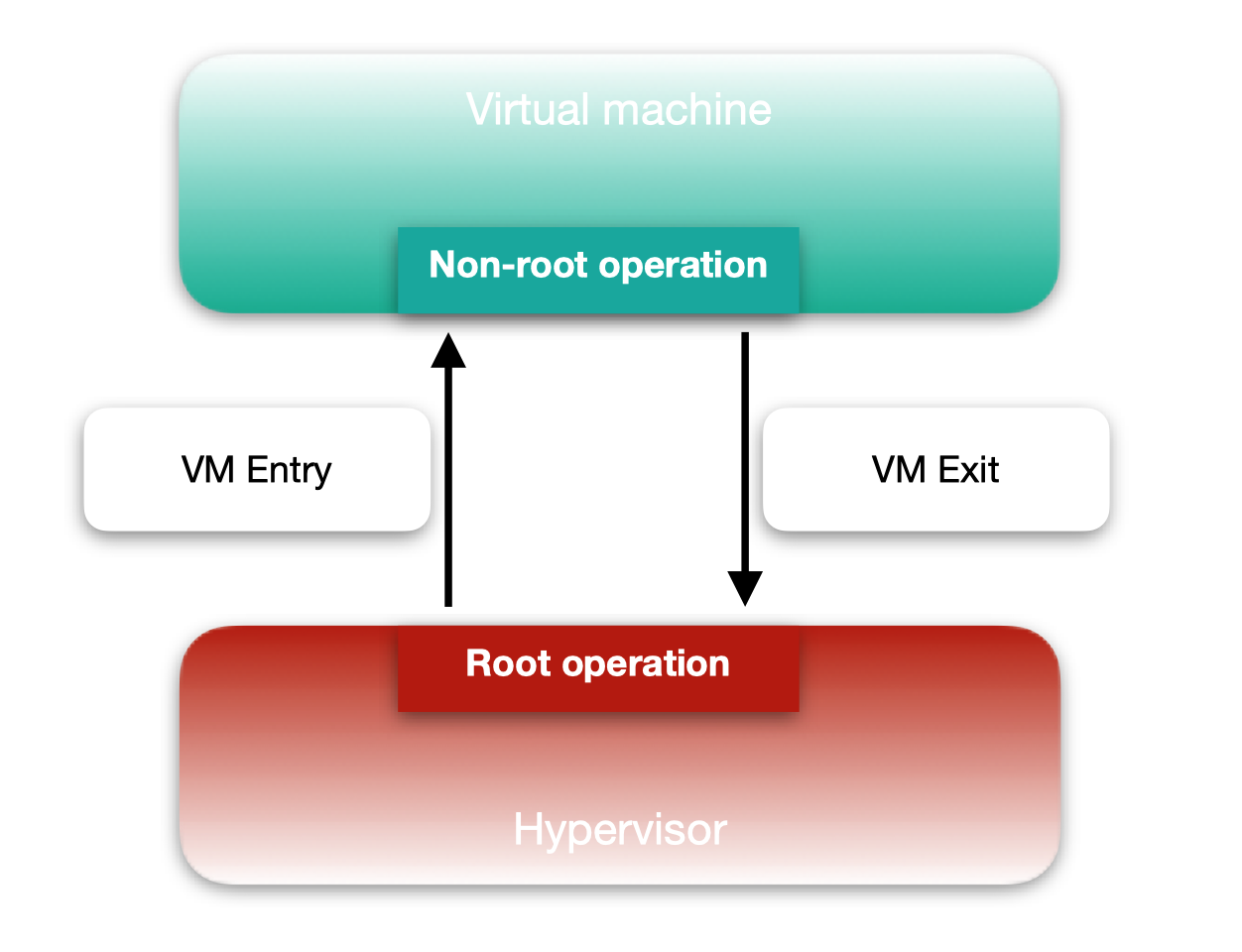
As rings are present in an operating system to separate the level of privilege between programs running in ring 0 and others running in ring 3, virtualization defines VMX mode operations that distinguish between two different modes of executions:
VMX root operation when the Hypervisor (host) process is running;
VMX non-root operation when a process in a virtual machine (guest) is running.
The transition between the two modes is called a VMX transition and is triggered upon the occurrence of a defined types of events. A VMX transition from non-root to root mode, hence an exit from the virtual machine to the hypervisor is called a VM Exit. In the other direction, a VMX transition from the hypervisor to a virtual machine is called a VM Entry.
The transitions are managed and controlled by the hypervisor that relies heavily on a structure named the Virtual Machine Controlling Structure (VMCS).
VMCS
VMX transitions require saving the processor state before exiting a VMX mode and restoring the appropriate processor state of the one it is entering. The VMCS serves this purpose, as it contains a host area that aims to hold the processor state of the hypervisor/host, which is either saved or used for restoring, depending on whether it is performing a VM Entry or a VM Exit.
A guest area, in turn, is present in the VMCS for the same purpose with the difference that it holds the processor state of the VMX non-root mode, specifically the memory state of the process that caused the VM Exit, on a specific virtual processor of the virtual machine. As a result, there can be multiple VMCS, following the number of virtual processors a virtual machine has.
When a VM Exit occurs, execution returns to the VMX root operation, and specifically to the VM Exit handler within the hypervisor's code. This handler is in charge of taking the proper action following the reason that triggered the VM Exit. VM Exit reasons can be quite different, but luckily their codes can be found in the documentation [2] and can easily be deployed as an enum in the disassembler.
FFFFFFFF ; enum VMExit_reason, mappedto_14
FFFFFFFF EXIT_REASON_EXCEPTION_NMI  = 0
FFFFFFFF EXIT_REASON_EXTERNAL_INTERRUPT  = 1
FFFFFFFF EXIT_REASON_TRIPLE_FAULT  = 2
FFFFFFFF EXIT_REASON_INIT  = 3
FFFFFFFF EXIT_REASON_SIPI  = 4
FFFFFFFF EXIT_REASON_IO_SMI  = 5
FFFFFFFF EXIT_REASON_OTHER_SMI  = 6
FFFFFFFF EXIT_REASON_PENDING_VIRT_INTR  = 7
FFFFFFFF EXIT_REASON_PENDING_VIRT_NMI  = 8
FFFFFFFF EXIT_REASON_TASK_SWITCH  = 9
FFFFFFFF EXIT_REASON_CPUID  = 0Ah
FFFFFFFF EXIT_REASON_GETSEC  = 0Bh
FFFFFFFF EXIT_REASON_HLT  = 0Ch
These values are used in the code of the VM Exit handler, where a big switch case compares them to the actual reason that caused the VM Exit in a virtual machine.
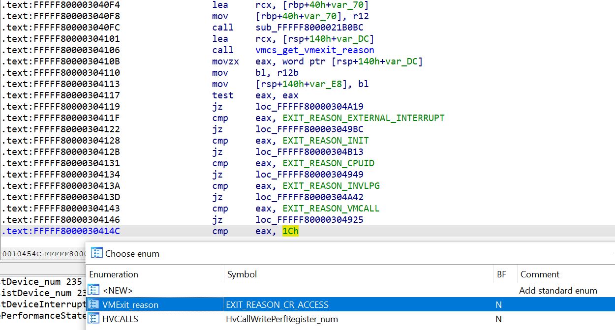
The function vmcs_get_vmexit_reason called at FFFFF80000304106 is in charge of reading the VM Exit reason from the appropriate VMCS. The following excerpt shows the code of this function where a code representing the `VM_EXIT_REASON` is used with the VT-x instruction vmread. In Intel VT-x the VMCS is an internal structure to the processor with an unknown layout to the software. Hence, Intel provides the vmread/vmwrite VT-x instructions to read and write respectively fields from the current VMCS, in VMX root operation, provided the code associated to the VMCS field.
.text:FFFFF80000302892
.text:FFFFF80000302892 loc_FFFFF80000302892:                   ; CODE XREF: vmcs_get_vmexit_reason+D↑j
.text:FFFFF80000302892                 mov     eax, VM_EXIT_REASON
.text:FFFFF80000302897                 vmread  rax, rax
.text:FFFFF8000030289A                 mov     [rcx], eax
.text:FFFFF8000030289C                 retn
.text:FFFFF8000030289C vmcs_get_vmexit_reason endp
The VM_EXIT_REASON code is defined as 0x4402 in Intel documentation [2], and is necessary as an operand to both vmread/vmwrite instructions:
FFFFFFFF VM_INSTRUCTION_ERROR  = 4400h           ; XREF: vmcs_get_VM_INSTRUCTION_ERROR
FFFFFFFF VM_EXIT_REASON   = 4402h                ; XREF: vmcs_get_VM_EXIT_REASON+E/s
However, we can notice that neither of the 2 VT-x instructions require the address of the VMCS from which the access is performed, as they both operate on the current VMCS, in VMX root operation.
In order to know on which VMCS the read/write access occurs, Intel VT-x provides the vmptrst instruction for extracting the physical address of the current VMCS.
loc_FFFFF8000030BD1C:
mov     [rsp+48h+var_28], r14
vmptrst [rsp+48h+var_28]
mov     rax, [rsp+48h+var_28]
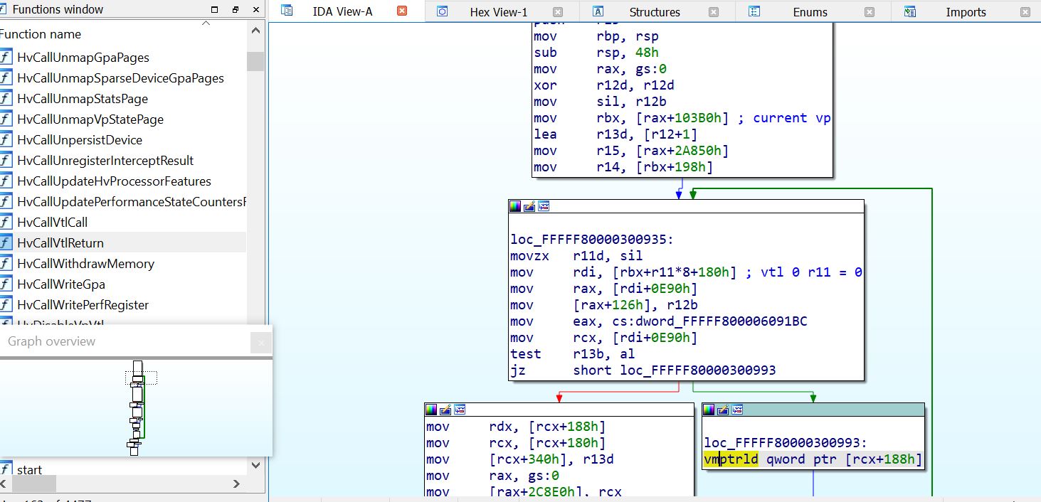
While switching to another VMCS requires its physical address as an operand to the vmptrld VT-x instruction.
.text:FFFFF80000300993 loc_FFFFF80000300993:                   ; CODE XREF: sub_FFFFF800003008F8+67↑j
.text:FFFFF80000300993                 vmptrld qword ptr [rcx+188h]
When debugging a hypervisor, putting a breakpoint on the vmptrld instruction reveals that there can be several different VMCS physical addresses as operand to the instruction. This can be the case even when there is a single virtual machine running.
While one might think that a VMCS is proper to a virtual machine, it is instead affiliated specifically to its virtual processors. Each virtual processor has at least one VMCS, so when running a virtual machine with _X_ virtual processors, at least _X_ VMCS are present.
There are some cases where there can be more than one VMCS associated to a virtual processor. This will be seen further in the blogpost during reverse engineering Hyper-V.
To summarize, the VMCS is a memory region, often in a 4KB memory page, that can be accessed by the hypervisor through its physical address, to control and manage the running virtual machines.
It plays a key role in the VMX transitions, in order to keep track of the execution in both the VMX root and non root operations, and it further can be used to control the execution within the virtual machines.
Some additional areas are present in the VMCS, that are responsible for modifying the virtual machine behaviour, such as adding new possible VM Exit reasons that will force a VM Exit from the virtual machine, while some other fields will force a VM Entry to the virtual machine.
Second Level Address Translation
Apart from the VMX operations and handling virtual machines with the help of VMCS, hardware virtualization adds an extended layer in the paging mechanism. As we know it, through pagination virtual memory abstracts the physical hardware memory, as programs only see their virtual address space. Two processes can access the same virtual address that points to different physical memory addresses.
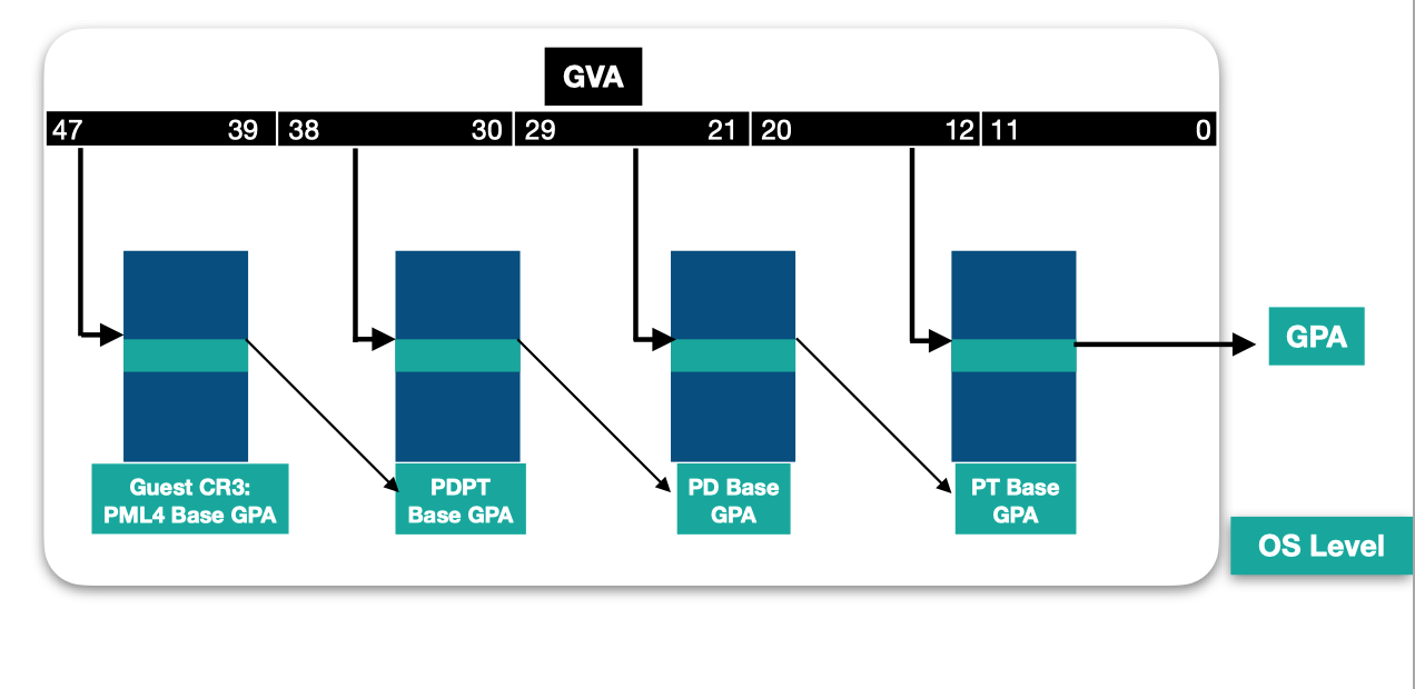
This is possible thanks to the address translation in the processor, where each virtual address is a bitfield that encodes offsets in tables used for address translation in a page-table walk. Each entry read in a table references the physical address of the next table base. When the last table is hit, the entry read, called the Page Table Entry (PTE), contains the frame number of the resulting physical page, and its access rights.
The page walk starts from the PML4 table, whose address is referenced by the CR3 register in the context of the process that tries to perform the access.
Hardware virtualization introduces a new layer in the address translation process, by adding a new level in the tables hierarchy. Called "Second Level Address Translation (SLAT)" or nested-paging, this hardware virtualization feature enables to virtualize the physical memory of the guest machine. It lies on the extended page-table mechanism (EPT) which defines 4 different address spaces:
GVA (Guest Virtual Addresses) - virtual addresses as seen by the processes running in the virtual machine;
GPA (Guest Physical Addresses) - physical addresses as seen by the virtualized Operating System as physical memory;
SVA (System Virtual Addresses) - virtual addresses as seen by the hypervisor process;
SPA (System Physical Addresses) - physical addresses that point to the effective physical memory in the underlying hardware;
System virtual addresses represent the virtual memory address space seen by the hypervisor process, that runs on top of the hardware. As a result, it is not subject to the second level address translation, and is translated following the normal page-table walk starting from the PML4 table of the process, found in its CR3 register. The result of this address translation is a PTE with the frame number that can be used to access the System Physical Address in the hardware memory.
However, the concept of Guest physical and virtual addresses are specific to virtualization, as a level of abstraction is added when running a virtual machine. EPT increases the hierarchy table and defines a new layer of tables. At the virtual machine level, a GVA is a virtual address that translates to a GPA through the normal page-table walk. Even if considered as physical address at the guest level, each accessed Guest physical address in the page tables, is itself a bitfield that requires to be translated to the System Physical Address in order to access the real physical memory.
Address translation from a Guest Physical Address to a System Physical Address follows the same process of a normal address translation from a virtual to a physical address, except for the tables used in the address translation. The first table required for a translation from a GPA to an SPA is named EPT PML4 table, and its base is referenced by a pointer named Extended Page Table Pointer - EPTP, that can be found in the VMCS of the virtual machine's virtual processors.
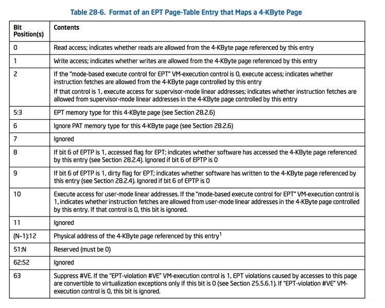
The EPTP encodes from its 12th bit the physical address of the EPT PML4 table base.
EPTP format
2:0     : Memory type = 6 => Uncacheable (UC)
5:3     : Ept table walk -1
6   : Dirty flags
11:7    : Reserved
N-1:12  : Physical address of the 4-KByte aligned PML4 Table
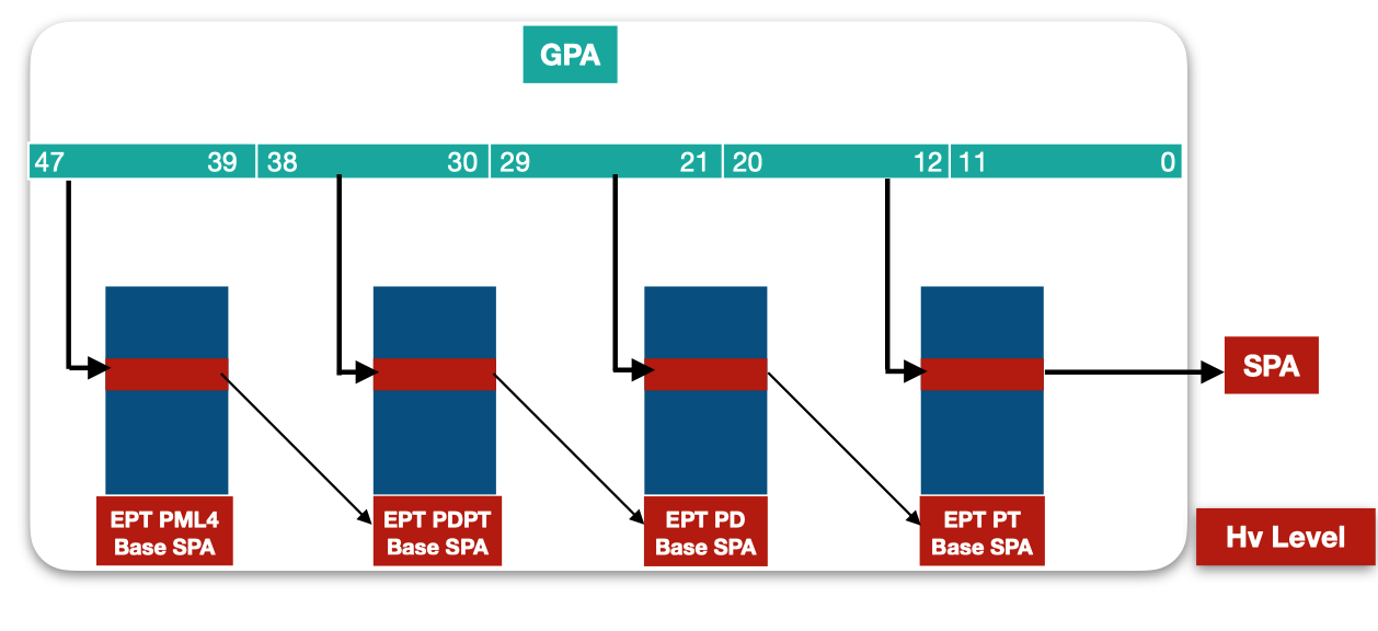
The page-table walk takes place in the EPT tables, and the resulting EPT Page Table Entry holds the system physical address of the page and its effective access rights. If a ring 0 process within the virtualized operating system can’t access the EPT PTE, it is then unable to have an impact on its access rights.
Just like two processes, running with pagination enabled, have two different PML4 table base and consequently different views of the physical memory using the same virtual address, using different EPTPs pointing to different EPT PML4 tables, the same Guest Physical Address can translate to different System Physical Addresses with different access rights.
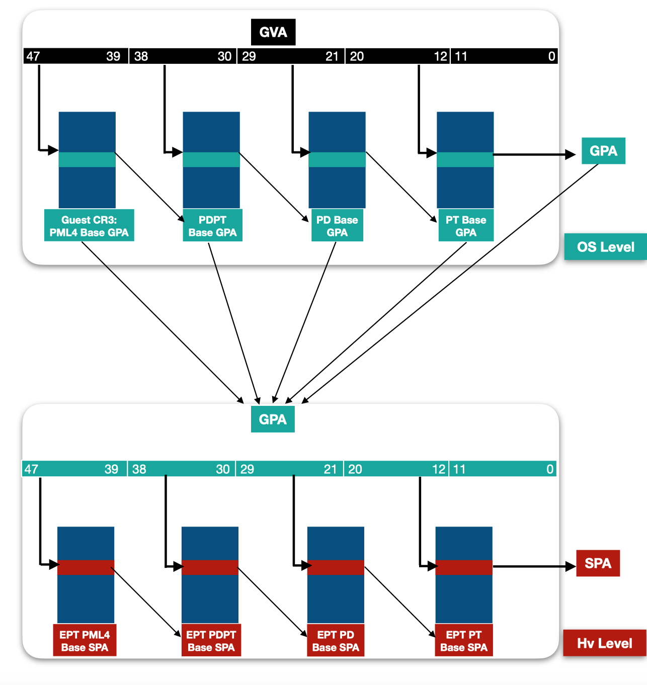
Considering that each entry in the tables accessed by the OS is a GPA that requires to be translated to an SPA, an address translation of a GVA to SPA involves walking the 2 levels of tables as the following shows:
Hyper-V
Now that we established the minimal basics on hardware virtualization, we can move to reverse engineering and debugging Microsoft's hypervisor, Hyper-V. Hyper-V is a type-1 hypervisor, called bare-metal, as it runs directly on the hardware. It became an important part of Microsoft's operating system architecture as a great number of security features of Windows lies on virtualization. A few years ago, credential stealing could easily be performed using Mimikatz to read lsass.exe memory. Today, using this technique even with administrative rights on a Windows 10 with VBS enabled would fail. In this part, we aim to know how this was made possible by Hyper-V.
Partitions
Hyper-V manages the isolation of its virtual machines in terms of partitions. In Microsoft terminology, a virtual machine is called a Partition, and they exist in 2 different flavors. The first is the root partition. It is the main Windows Operating System running on top of Hyper-V. It includes a great part of the virtualization stack, in order to minimize the code quantity within the hypervisor and reduce its surface attack. Through issuing specific calls to the hypervisor, the root partition can create and manage other partitions, which brings us to the second kind of partitions: the child partitions. The child partitions are the guest virtual machines running on top of the root partition, they are less privileged in accessing the hypervisor's resources, opposed to the root that participates greatly in the virtualization tasks. The resources include hypercalls and Model Specific Registers, and can be found in Microsoft' Hyper-V TLFS [3]. A partition can have one or more virtual processors, identified by its partition identifier and its processor index. Each virtual processor has its own registers, interrupts, and intercepts.
Virtual Trust Levels
With VSM enabled, within the same partition, a new world appears, dubbed the secure world. It runs a secure kernel in ring 0, with a limited number of userland processes running in ring 3 called trustlets. The creation of the Virtual Trust Levels comes directly from the need of creating a segregation that sets boundaries between different memory regions: the normal and the secure worlds.
A VTL is attributed to a virtual processor (VP for short). There can be a total of 16 VTLs, and they are hierarchical. At the time being Microsoft chose to only implement 2 VTLs: VTL 0 and VTL 1. The lower a VTL, the least privileged it is. A lower VTL can use a higher one to store its secrets or conduct sensitive operations.
In Windows architecture, the normal NT kernel with the userland processes run in the VTL 0. As opposed to it, the new security features are running in VTL 1, thus the SecureKernel and the trustlets. In this model, the NT kernel becomes outside the chain of trust. The secure world runs minimal code, essentially cryptographic and communication protocols as RPC, while the regular OS features are kept in the normal NT kernel. The two kernels communicate with each other and need to work together for proper functioning. The secure world provides to the normal world safe ways to keep secrets and run sensitive security algorithm checks, while the normal kernel provides the usual OS features to the secure world, like memory allocation, etc.
Hyper-V structures
Hyper-V keeps track of the current state, such as the current running partition, current virtual processor, current VMCS, etc. These information are represented as objects in memory pointed by the primary gs structure, as stated by Saar Amar in Microsoft's blogpost about reverse-engineering Hyper-V [4]. They can easily be found, as most hypercalls check if the calling partition is allowed to perform the call through checking its permissions flag.
HvCallDeletePartition proc near

arg_0= qword ptr  8

mov     [rsp+arg_0], rbx
push    rdi
sub     rsp, 20h
mov     rax, gs:103A8h
mov     rdi, rcx
mov     rdx, [rax+128h]
mov     rax, 100000000h
test    rax, rdx
jnz     short loc_FFFFF800002900D3
In the excerpt above, the HvCallDeletePartition function first checks if the permission at offset 128 of the current Partition structure pointed by gs:103A8 is allowed to perform the call.
0: kd> rdmsr 0xc0000101
msr[c0000101] = fffff87d`63fa6000

0: kd> dq fffff87d`63fa6000 + 0x103A8
fffff87d`63fb63a8  ffffe800`00001000 ffffe800`00669050
The current running partition structure is at 0xffffe80000001000. While the current virtual processor is pointed by gs:103A0.
0: kd> dq fffff87d`63fa6000 + 0x103A0
fffff87d`63fb63a0  ffffe800`00669050 ffffe800`00001000

: kd> dq ffffe800`00001000 L100
ffffe800`00001000  00000000`00000000 00000000`00000000
ffffe800`00001010  00000000`00000000 ffffe800`00001018
ffffe800`00001020  ffffe800`00001018 00000000`00000000
ffffe800`00001030  00000000`00000000 ffffe800`00001038
ffffe800`00001040  ffffe800`00001038 00000000`00000000
ffffe800`00001050  00000000`00000000 ffffe800`00001058
ffffe800`00001060  ffffe800`00001058 00000000`00000000
ffffe800`00001070  00000000`00000000 ffffe800`00001078
ffffe800`00001080  ffffe800`00001078 00000003`00000000
ffffe800`00001090  00000000`00000000 00000001`00000010
ffffe800`000010a0  00000000`00000000 00000000`00000000
ffffe800`000010b0  00000000`00000000 00000000`00000000
ffffe800`000010c0  00000000`00000000 00000000`00000000
ffffe800`000010d0  00000000`00000000 00000000`00000000
ffffe800`000010e0  00000000`00000000 00000000`00000000
ffffe800`000010f0  00000000`00000000 00000000`00000000
ffffe800`00001100  00000000`00000000 00000000`00000000
ffffe800`00001110  00000000`00000000 00000000`00000000
ffffe800`00001120  00000000`01017843 002bb9ff`00003fff
ffffe800`00001130  ffffe800`00000000 00000000`00000000
ffffe800`00001140  ffffe800`0063c7f0 00000003`00000004
ffffe800`00001150  00000000`00000000 ffffe800`00669050
ffffe800`00001160  ffffe800`00770050 ffffe800`00793050
ffffe800`00001170  ffffe800`007b1050 00000000`00000000
ffffe800`00001180  00000000`00000000 00000000`00000000
At the offset 0x128 of the Partition structure we can extract the privileges of the partition, with value 002bb9ff00003fff. Its binary representation encodes the hypercalls and MSRs that the partition is allowed to access.
>>> bin(0x002bb9ff00003fff)
1 0 1 0 1 1 1 0 1 1 1 00 111111111 000000000000000000 11111111111111
Access to Hypercalls              |  Reserved        |Access to MSRs
Based on the hypervisor resources allowed, we can determine that the discovered partition is the root partition. (For more information, check the HV_PARTITION_PRIVILEGE_MASK structure in Hyper-v TLFS [3]).
Comparing this value with the privileges (0038803000002e7f) of another partition found at 0xffffe80200001000
2: kd> dq 0xffffe80200001000 + 0128
ffffe802`00001128  00388030`00002e7f
The second partition seems to be less privileged as it has access to a very limited number of hypercalls.
>>> bin(0x38803000002e7f)
1 1 1 0 0 0 1 0 0 0 0 00 000110000 000000000000000000 10111001111111
Access to Hypercalls              |  Reserved        |Access to MSRs
We can conclude that it is a child partition.
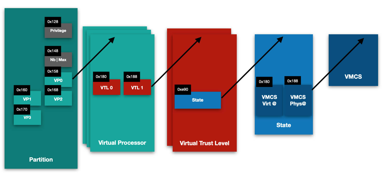
Aside from the privilege flags, the partition structure holds information about the number of virtual processors it has, and the address of each virtual processor structure associated to it.
During the virtual processor creation, analysis of the HvCallCreateVp hypercall shows a call to the sub_FFFFF8000029FA64 function. It updates the partition structure, referenced by the RDI register in the following code, by incrementing the number of virtual processors, the maximum virtual processor ID, and affects the virtual processor structure address to the offset 0x158 added to the VP id*8.
.text:FFFFF8000029FBA3                 mov     [rdi+14Ch], r15d ; max VP id
.text:FFFFF8000029FBAA
.text:FFFFF8000029FBAA loc_FFFFF8000029FBAA:                   ; CODE XREF: sub_FFFFF8000029FA64+13D↑j
.text:FFFFF8000029FBAA                 mov     rcx, rdi
.text:FFFFF8000029FBAD                 call    sub_FFFFF800002A20DC
.text:FFFFF8000029FBB2                 mov     rax, [rbp+4Fh+var_28]
.text:FFFFF8000029FBB6                 mov     rcx, rdi
.text:FFFFF8000029FBB9                 mov     [rdi+r15*8+158h], rax ; r15= VP number, rdi= partition
.text:FFFFF8000029FBC1                 call    sub_FFFFF800002A20DC
.text:FFFFF8000029FBC6                 inc     dword ptr [rdi+148h] ; number of VPs
Hence, the following information can be added to the partition structure:
offset 0x148: the number of virtual processors;
offset 0x14C: the maximum identifier of the virtual processors, the first one being at ID = 0;
offset 0x158: the first virtual processor structure address (id=0).
Based on the debugger excerpt:
2: kd> dq ffffe800`00001000 + 0x140
ffffe800`00001140  ffffe800`0063c7f0 00000003`00000004
ffffe800`00001150  00000000`00000000 ffffe800`00669050
ffffe800`00001160  ffffe800`00770050 ffffe800`00793050
ffffe800`00001170  ffffe800`007b1050 00000000`00000000
We can confirm that:
0xffffe80000001000 + 0x148: The partition has 4 different virtual processors;
0xffffe80000001000 + 0x14C: The maximum virtual processor index is 3;
0xffffe80000001000 + 0x158: Virtual Processor 0 is at 0xffffe80000669050;
0xffffe80000001000 + 0x160: Virtual Processor 1 is at 0xffffe80000770050;
0xffffe80000001000 + 0x168: Virtual Processor 2 is at 0xffffe80000793050;
0xffffe80000001000 + 0x170: Virtual Processor 3 is at 0xffffe800007b1050.
Hunting the Virtual Machine Controlling Structure
Since the VMCS plays an essential role in managing partitions, now that we found the partition and virtual processor structures, we aim to find the reference to the VMCS physical address of the VP.
Based on the acquired knowledge on VMX, targeting the VT-x instruction that manipulates the VMCS seemed like a good starting point.
As we saw earlier, vmptrld takes as an operand a VMCS physical address. Going from that point, the instruction is fetched in the disassembly code of the hvix64.exe binary, with the goal of finding where the hypervisor stores this kind of addresses, and from where they can be referenced.
The VMCS physical address is often picked at the offset 0x188 added to a pointer. If we consider that RCX holds the address of a stucture named Struct1, at offset 0x188 of the structure a VMCS physical address is found.
.text:FFFFF80000300993 vmptrld qword ptr [rcx+188h]
hv+0x30c848:
fffff846`eb70c848 0fc7b188010000  vmptrld qword ptr [rcx+188h]
kd> r rcx
rcx=ffffe8000066d188
kd> dd [rcx+188]
ffffe800`0066d310  0e32f000 00000001 00678000 ffffe800
Breakpoint 3 hit
hv+0x22697f:
fffff846`eb62697f 0fc7b188010000  vmptrld qword ptr [rcx+188h]
kd> dd rcx+188
ffffe800`0066b310  0e32b000 00000001 00674000 ffffe800
Struct1 's address is extracted from the offset 0xe90 of a second structure, that we choose to name Struct2.
.text:FFFFF80000300955 mov rcx, [rdi+0E90h]
Following the same process, Struct2 is referenced by a third structure, Struct3, at the offset 0x180 added to an index multiplied by 8.
.text:FFFFF80000300939 mov rdi, [rbx+r11*8+180h]
The base of Struct3 is in turn pointed by the structure referenced by the GS register, at offset 0x103B0.
.text:FFFFF8000030090C                 mov     rax, gs:0
...
.text:FFFFF8000030091B                 mov     rbx, [rax+103B0h]
This address points to a virtual processor structure. We see a bit further in the code that this address is compared to the one of the current virtual processor structure pointer:
.text:FFFFF80000258907                 mov     rdi, [rsi+103B0h]
.text:FFFFF8000025890E                 test    rdi, rdi
.text:FFFFF80000258911                 jz      loc_FFFFF80000258B18
.text:FFFFF80000258917                 cmp     rdi, [rsi+103A0h]
.text:FFFFF8000025891E                 jnz     loc_FFFFF80000258B18
.text:FFFFF80000258924                 mov     eax, gs:8
For now, we can assert the following:
GS at offset 0x103B0: Virtual Processor;
Virtual Processor at offset 0x180 + index*8: Struct2;
Struct2 at offset 0xe90: Struct1;
Struct1 at offset 0x180: VMCS Physical Address.
At this point, we seem to have found a correlation between the VP and the VMCS address. However, we need to define the two structures Struct1 and Struct2.
If we look back at the Virtual Processor structure layout, specifically at the offset 0x180:
0: kd> dq ffffe800`00669050 +0x180 L80
ffffe800`006691d0  ffffe800`0066a000 ffffe800`0066c000
ffffe800`006691e0  00000000`00000000 ffffe800`0066a000
Provided:
the index 0, Struct2 would be at ffffe8000066a000;
the index 1, Struct2 would be at ffffe8000066c000.
We notice that both offsets 0x180 and 0x198 contain the same address, consequently offset 0x198 points to a Struct2 as well.
The following excerpt displays the memory layout of these structures. We notice that the virtual processor is referenced at offset 0.
0: kd> dq ffffe800`0066a000
ffffe800`0066a000  ffffe800`00669050 ffffe800`0066ae80

0: kd> dq ffffe800`0066c000
ffffe800`0066c000  ffffe800`00669050 ffffe800`0066ce80
However, the two structures have at their offset 0xe90 different Struct1 pointers, which in turn hold 2 different VMCS physical addresses, and consequently two different memory states.
In order to find a proper definition of Struct1 and Struct2, we take a step back to dive into the Hyper-V TLFS, which states: "Virtual processors maintain separate states for each active VTL. State which is preserved per VTL (a.k.a. private state) is saved by the hypervisor across VTL transitions. If a VTL switch is initiated, the hypervisor saves the current private state for the active VTL, and then switches to the private state of the target VTL."[3].
We suppose that Struct2 represents the Virtual Trust Level. The one at index 0 being VTL 0, while the one at index 1 is the VTL 1. Hence, Struct1 represents the memory state of the VTL including the VMCS address.
We verify this information through monitoring the hypercalls that allow to switch VTLs.
VTL switch
A VP can switch VTLs; depending if it is entering a higher or a lower VTL, we call it respectively a VTL call and VTL return.
VTL Return
A VTL return is when a higher VTL initiates a switch into a lower VTL. Static analysis on HvCallVtlReturn shows that the function checks the index of the VTL before performing the switch, if it is equal to zero a jump to the end of the function occurs.
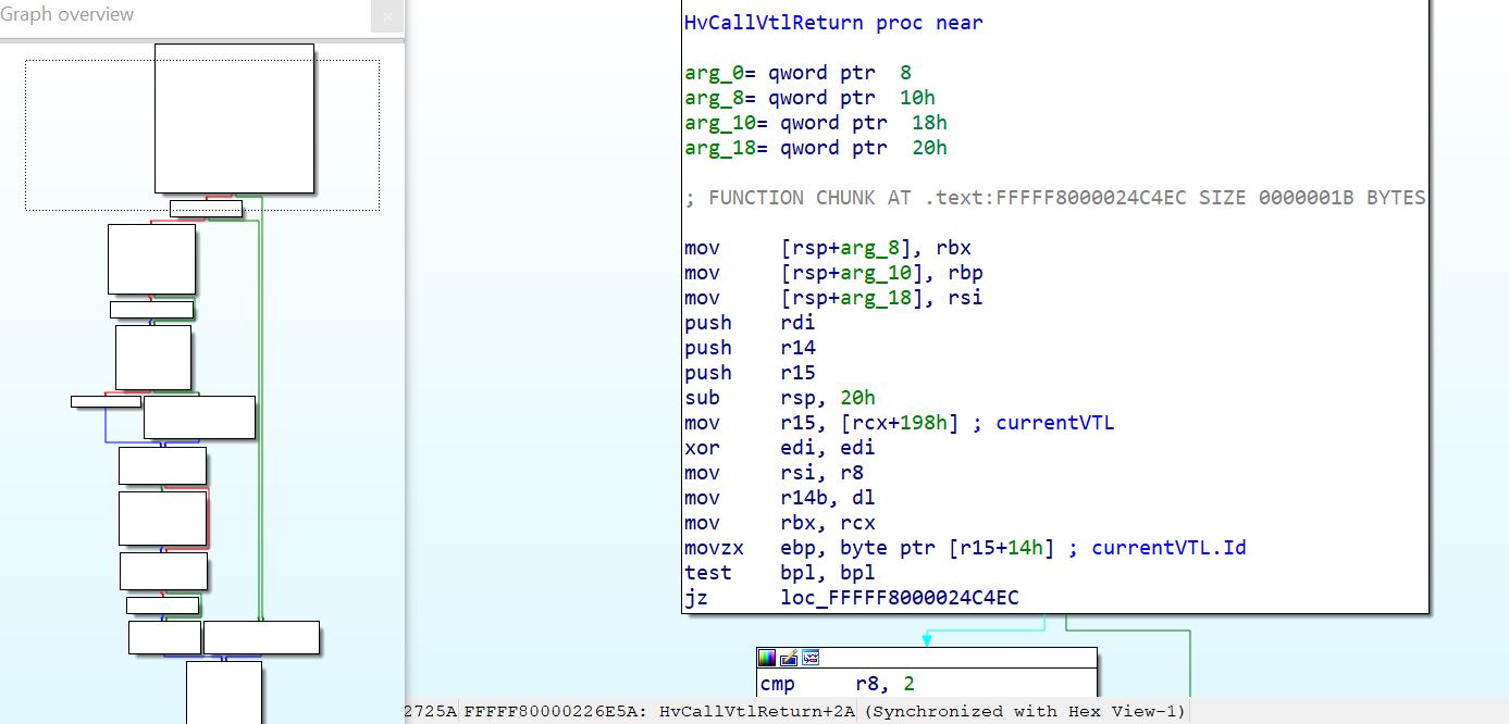
The byte containing the index of the VTL is at the offset 0x14 in our version, while the current VTL structure is referenced at the offset 0x198 of the virtual processor structure.
Using the debugger, a breakpoint is set at the start of the hypercall function HvCallVtlReturn, to analyze data at the aforementioned offsets.
The following excerpt displays the memory context at the start of the HvCallVtlReturn hypercall:
============ Partition ============
gs:[103a8] = Current Partition:  ffffe80000001000
Current Partition Privileges:  2bb9ff00003fff
============ Virtual Processor ============
gs:[103a0] = Current VP:  ffffe80000669050
VP:[1d4] = VP ID: 0
============ Current VTL ============
VP:[198] = Current VTL:  ffffe8000066c000
VTL:[14] = Current VTL ID :  1
STATE:[188] = VMCS physical Address:  10e32e000
STATE:[180] = VMCS virtual Address: ffffe80000676000
A breakpoint set at the end of the hypercall reveals that the Current VP with ID 0 has switched from VTL 1 to VTL 0, with a switch of the memory context.
============ Partition ============
gs:[103a8] = Current Partition:  ffffe80000001000
Current Partition Privileges:  2bb9ff00003fff
============ Virtual Processor ============
gs:[103a0] = Current VP:  ffffe80000669050
VP:[1d4] = VP ID: 0
============ Current VTL ============
VP:[198] = Current VTL:  ffffe8000066a000
VTL:[14] = Current VTL ID :  0
STATE:[188] = VMCS physical Address:  10e32a000
STATE:[180] = VMCS virtual Address: ffffe80000672000
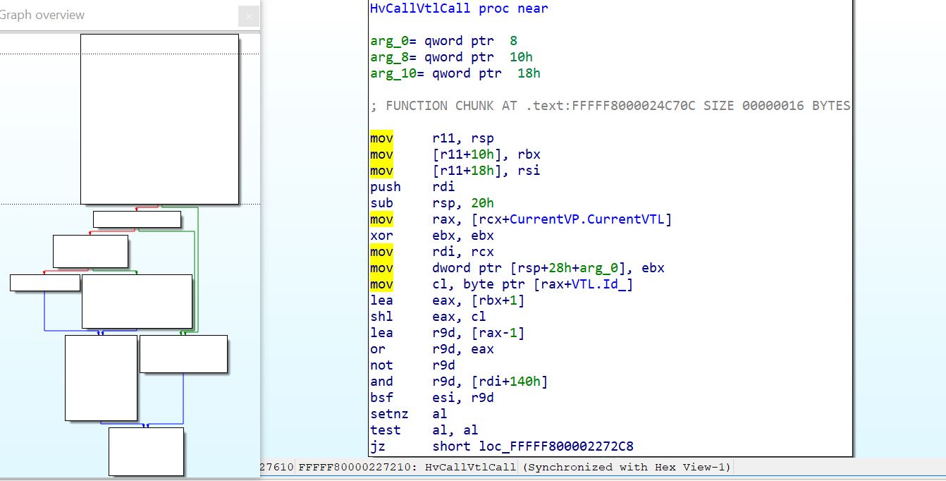
VTL Call
A VTL call is when a lower VTL initiates a switch into a higher VTL. This can be performed to store secrets into VTL 1 through the HvCallVtlCall hypercall. The hypercall starts by analyzing the value of the current virtual processor's VTL index, as VTL 1 is the highest allowed.
Based on the extracted offsets, using a Windbg script we analyse the different values of interest at the start of the HvCallVtlCall hypercall and at the end of it.
The following memory excerpt displays that the VP initiating the VTL Return is VP 2, with VTL 0. The Current VTL structure is addressed at ffffe80000794000 which has the index 0.
============ Partition ============
gs:[103a8] = Current Partition:  ffffe80000001000
Current Partition Privileges:  2bb9ff00003fff
============ Virtual Processor ============
gs:[103a0] = Current VP:  ffffe80000793050
VP:[1d4] = VP ID: 2
============ Current VTL ============
VP:[198] = Current VTL:  ffffe80000794000
VTL:[14] = Current VTL ID :  0
STATE:[180] = VMCS virtual Address:  ffffe8000079c000
STATE:[188] = VMCS physical Address:  430c67000
At the end of HvCallVtlCall, the value of the Current VTL changes to ffffe80000796000 which has the index 1. As a result, the Virtual Trust Level of the virtual processor 2 has switched from zero to the next Virtual Trust Level = 1. In the same line, the memory context of the virtual processor is switched and is controlled by the VMCS at the System Physical Address 0x430c6a000.
============ Partition ============
gs:[103a8] = Current Partition:  ffffe80000001000
Current Partition ID:  0
Current Partition Privileges:  2bb9ff00003fff
============ Virtual Processor ============
gs:[103a0] = Current VP:  ffffe80000793050
VP:[1d4] = VP ID: 2
VP:[1c4] = VP VTL: 1
============ Current VTL ============
VP:[198] = Current VTL:  ffffe80000796000
VTL:[14] = Current VTL ID :  1
STATE:[180] = VMCS virtual Address:  ffffe8000079f000
STATE:[188] = VMCS physical Address:  430c6a000
Hence, the structure that we named earlier Struct1 (referenced at offset 0xe90 of Struct2) holds information about the private state of the VTL, including the VMCS properties: the virtual and physical addresses at offsets 0x188 and 0x180.
Going back to the discovered VP structure at ffffe80000669050:
0xffffe8000066a000: references the VTL 0 structure;
0xffffe8000066c000: references the VTL 1 structure;
0xffffe8000066a000: references the current VTL structure (VTL 0).
For VTL 0 of VP0, the VMCS structure is at 0xffffe8000066b188.
0: kd> dq ffffe800`0066a000+e90
ffffe800`0066ae90  ffffe800`0066b188
Once in the VTL state (where we find VMCS properties) structure, offsets 0x180 and 0x188 provide respectively the system virtual and physical addresses of the VMCS.
0: kd> dq ffffe800`0066b188+180
ffffe800`0066b308  ffffe800`00672000 00000001`0e586000
The VMCS’ physical address for (VP 0,VTL 0) is 0x10e586000, while its system virtual address is 0xffffe80000672000.
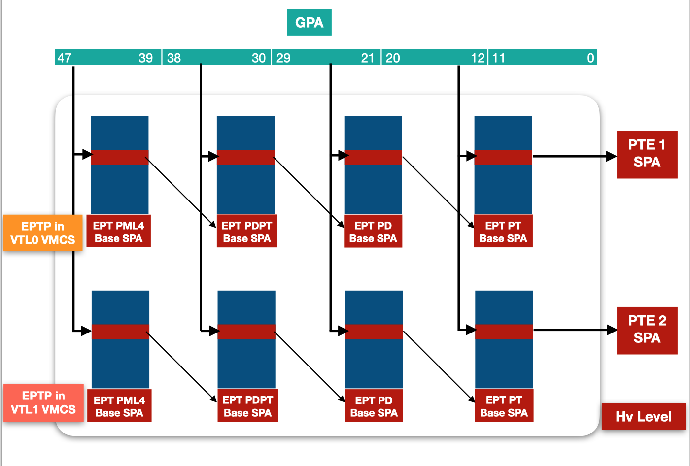
For single virtualization purposes, having one VMCS per VP is enough, however Microsoft chose in its implementation of Hyper-V, to affect a VMCS to a VTL when VSM is enabled instead. This choice allows to have within the same partition, different Virtual Trust Levels. Switching VTLs on a VP induces a switch on the processor state through a switch of VMCS. Each VTL has its own intercepts, interruptions, and memory layout starting by different EPTPs in the VMCS.
A VMCS is therefore affected in Hyper-V’s architecture with VSM enabled, to a pair (VP, VTL).
Access VTL 1 memory from VTL 0
Exploring the VMCS layout, following the processor used, we recognized the EPTP at offset 0xe8, while the guest CR3 is at offset 0x2e0. Provided these two values, the Second Layer Address Translation can be performed from the hypervisor context on any Guest Virtual and Physical Addresses, whether in VTL0 or VTL1.
For the following, we will extract the SecureKernel's base address, and translate it to its SPA. Following that, we will map the resulting SPA to the normal kernel's address space.
SLAT of a memory address in VTL 1
During the boot section, the root partition’s debugger displays the SecureKernel virtual image base address 0xFFFFF80773600000.
SecureKernel virtual image base = 0xFFFFF80773600000 Image size = 0xfe000 Entry point = 0xFFFFF80773633668
First we extract the EPTP from the VMCS of the (VP 0, VTL 1) pair:
EPTP: 0x11070d01e;
The Guest CR3 is extracted from the VMCS of a VTL 1, and it must be the SecureKernel that caused a VM Exit, in order to get its CR3:
GUEST CR3: 0x6c00002.
EPT translation: GPA to SPA
The first step for address translation is to translate the Guest CR3 GPA to its SPA. Considered as a bitfield, the GPA 0x6c00000 is used to extract the offsets that will be used during the page-table walk:
PML4 offset: 0x0;
PDPT offset: 0x0;
PD offset 0x36;
PT offset 0x0;
Physical Page offset 0x0.
Starting from the EPT PML4, referenced by the EPTP, we proceed to the EPT 4-table page walk.
2: kd> dq /p 11070d000 L1
00000001`1070d000  80000001`10713163
2: kd> dq /p 80000001`10713000 L1
80000001`10713000  00000001`1073c507
2: kd> dq/p 00000001`1073c000 L1
00000001`1073c000  00000001`1072d507
2: kd> dq/p 00000001`1073c000 + 0x36*8 L1
00000001`1073c1b0  00000001`10775507
2: kd> dq /p 00000001`10775000 L1
00000001`10775000  08100000`06c00230
We notice that PML4 SPA = PML4 GPA = 0x6c00000. This is called the identity-mapping, for the root partition each GPA translates to itself as SPA. Each entry read from the virtual machine’s tables is a GPA, considering the identity mapping we will skip translation from GPA to SPA, as GPA = SPA.
Address translation from GVA to GPA
From the 0xfffff80773600000 GVA, we extract the offsets that will be used for page-table walk:
PML4 offset: 0x1f0;
PDPT offset: 0x1d;
PD: 0x19b;
PT: 0x0;
OFFSET: 0x0.
Since the running partition has the identity-mapping, GPA = SPA, thus only the GPA is computed from the GVA.
2: kd> dq /p 000`06c00000 + 0x1f0*8 L1
00000000`06c00f80  00000000`06c03063
2: kd> dq /p 000000`06c03000 + 0x1d*8 L1
00000000`06c030e8  00000000`06c02063
2: kd> dq /p 0000`06c02000 + 0x19b*8 L1
00000000`06c02cd8  00000000`06c01063
2: kd> dq /p 0000000`06c01000 L1
00000000`06c01000  80000000`04239021
The System Physical address of the SecureKernel is 0x4239000:
2: kd> db /p 000`04239000
00000000`04239000  4d 5a 90 00 03 00 00 00-04 00 00 00 ff ff 00 00  MZ..............
00000000`04239010  b8 00 00 00 00 00 00 00-40 00 00 00 00 00 00 00  ........@.......
00000000`04239020  00 00 00 00 00 00 00 00-00 00 00 00 00 00 00 00  ................
00000000`04239030  00 00 00 00 00 00 00 00-00 00 00 00 08 01 00 00  ................
00000000`04239040  0e 1f ba 0e 00 b4 09 cd-21 b8 01 4c cd 21 54 68  ........!..L.!Th
00000000`04239050  69 73 20 70 72 6f 67 72-61 6d 20 63 61 6e 6e 6f  is program canno
00000000`04239060  74 20 62 65 20 72 75 6e-20 69 6e 20 44 4f 53 20  t be run in DOS
00000000`04239070  6d 6f 64 65 2e 0d 0d 0a-24 00 00 00 00 00 00 00  mode....$.......
However access to the SecureKernel's physical address from the root partition debugger in VTL 0 context is restricted, as it is not mapped in the NT kernel's address space. As VTL 0 and VTL 1 have different VMCS with different EPTPs, they have different views of the memory layouts.
3: kd> db /p 000`04239000
00000000`04239000  ?? ?? ?? ?? ?? ?? ?? ??-?? ?? ?? ?? ?? ?? ?? ??  ????????????????
00000000`04239010  ?? ?? ?? ?? ?? ?? ?? ??-?? ?? ?? ?? ?? ?? ?? ??  ????????????????
00000000`04239020  ?? ?? ?? ?? ?? ?? ?? ??-?? ?? ?? ?? ?? ?? ?? ??  ????????????????
00000000`04239030  ?? ?? ?? ?? ?? ?? ?? ??-?? ?? ?? ?? ?? ?? ?? ??  ????????????????
00000000`04239040  ?? ?? ?? ?? ?? ?? ?? ??-?? ?? ?? ?? ?? ?? ?? ??  ????????????????
00000000`04239050  ?? ?? ?? ?? ?? ?? ?? ??-?? ?? ?? ?? ?? ?? ?? ??  ????????????????
00000000`04239060  ?? ?? ?? ?? ?? ?? ?? ??-?? ?? ?? ?? ?? ?? ?? ??  ????????????????
00000000`04239070  ?? ?? ?? ?? ?? ?? ?? ??-?? ?? ?? ?? ?? ?? ?? ??  ????????????????
Mapping memory pages from VTL 1 to VTL 0
In order to be able to access the SecureKernel memory from VTL 0, mapping its address to a VTL 0’s process physical address space is required. We will consequently map its SPA 0x4239000 to the NT kernel’s physical address space by creating the proper page table entries starting from the VTL 0’s EPTP.
We can choose to map it to any GPA. Since a GPA is considered as a bitfield from which the tables offsets are extracted, we choose a simple GPA such as 0x4000 that doesn’t require creating new tables.
0x4000 [EPT_PML4_idx] 0x0
0x4000 [EPT_PDPT_idx] 0x0
0x4000 [EPT_PD_idx] 0x0
0x4000 [EPT_PT_idx] 0x4
0x4000 [EPT_OFFSET] 0x0
Using the extracting indexes, we use the page-table walk starting from the EPT PML4 table base pointed by the EPTP.
EPTP = 0x1109d201e
EPT PML4E:
3: kd> dq /p 1109d2000 + 0*8 L1
00000001`109d2000  80000001`109d8163
EPT PDPTE:
3: kd> dq /p 001`109d8000 + 0*8 L1
00000001`109d8000  00000001`10601507
EPT PDE:
3: kd> dq /p 00001`10601000 + 0*8 L1
00000001`10601000  00000001`109f2507
Finally, at the EPT PTE value, we write the value 0x4239637 which is a valid entry.
3: kd> dq /p 01`109f2000 + 4*8 L1
00000001`109f2020  00000000`04239637
To ensure that access is granted, from the kernel debugger of the root partition, we inspect the memory at GPA 0x4000.
The following shows that we successfully achieved our goal, since access to the system physical memory content of the SecureKernel (running in VTL1) is granted to VTL0.
3: kd> db /p 000`00004000
00000000`00004000  4d 5a 90 00 03 00 00 00-04 00 00 00 ff ff 00 00  MZ..............
00000000`00004010  b8 00 00 00 00 00 00 00-40 00 00 00 00 00 00 00  ........@.......
00000000`00004020  00 00 00 00 00 00 00 00-00 00 00 00 00 00 00 00  ................
00000000`00004030  00 00 00 00 00 00 00 00-00 00 00 00 08 01 00 00  ................
00000000`00004040  0e 1f ba 0e 00 b4 09 cd-21 b8 01 4c cd 21 54 68  ........!..L.!Th
00000000`00004050  69 73 20 70 72 6f 67 72-61 6d 20 63 61 6e 6e 6f  is program canno
00000000`00004060  74 20 62 65 20 72 75 6e-20 69 6e 20 44 4f 53 20  t be run in DOS
00000000`00004070  6d 6f 64 65 2e 0d 0d 0a-24 00 00 00 00 00 00 00  mode....$.......
The SecureKernel SPA is accessible from the NT kernel process through the GPA: 0x4000. In order to map it to the NT kernel’s virtual address space, its CR3 register must be extracted. Then the same operation goes on by creating the different table entries implied in the process of address translation.
Windbg script to debug Hyper-V
As a helper, we provide a small script to retrieve the aforementioned structures and information when debugging Hyper-V. The script works on Hyper-V version 19041.21, and can be found at the following url: https://github.com/quarkslab/windbg-vtl.
It allows to:
Dump the existing partitions running on top of Hyper-V.
1: kd> dx -r1 @$scripts.hv.Contents.hvExtension.HvInternals.getPartitions()
    @$scripts.hv.Contents.hvExtension.HvInternals.getPartitions()                 : [object Generator]
        [0x0]            : _HV_PARTITION *[0xffffe80000001000]
        [0x1]            : _HV_PARTITION *[0xffffe80200001000]
List a partition’s properties
1: kd> dx -r1 @$scripts.hv.Contents.hvExtension.HvInternals.getPartitions()[0]
    @$scripts.hv.Contents.hvExtension.HvInternals.getPartitions()[0]                 : _HV_PARTITION *[0xffffe80000001000]
        PartitionProperty : 0x2bb9ff00003fff
        VirtualProcessorCount : 0x4
        VirtualProcessorList : Array of _HV_VP
        PartitionId      : 0x1
List a partition’s Virtual Processors
1: kd> dx -r1 @$scripts.hv.Contents.hvExtension.HvInternals.getPartitions()[0].VirtualProcessorList
    @$scripts.hv.Contents.hvExtension.HvInternals.getPartitions()[0].VirtualProcessorList                 : Array of _HV_VP
        [0x0]            : _HV_VP * [0xffffe80000669050]
        [0x1]            : _HV_VP * [0xffffe80000770050]
        [0x2]            : _HV_VP * [0xffffe80000793050]
        [0x3]            : _HV_VP * [0xffffe800007b1050]
List a virtual processor’s VTLs
1: kd> dx -r1 @$scripts.hv.Contents.hvExtension.HvInternals.getPartitions()[0].VirtualProcessorList[0].VtlList
    @$scripts.hv.Contents.hvExtension.HvInternals.getPartitions()[0].VirtualProcessorList[0].VtlList                 : Array of _HV_VTL
    [0x0]            : _HV_VTL * [0xffffe8000066a000]
    [0x1]            : _HV_VTL * [0xffffe8000066c000]
Find the structure that holds the properties of the VMCS associated to a partition’s VP-VTL:
1: kd> dx -r1 @$scripts.hv.Contents.hvExtension.HvInternals.getPartitions()[0].VirtualProcessorList[0].VtlList[0]
    @$scripts.hv.Contents.hvExtension.HvInternals.getPartitions()[0].VirtualProcessorList[0].VtlList[0]                 : _HV_VTL * [0xffffe8000066a000]
        VmcsProperties   : _HV_VMCS_PROPS * [0xffffe8000066b188]
Find a VMCS' physical & virtual addresses
0: kd> dx -r1 @$scripts.hv.Contents.hvExtension.HvInternals.getPartitions()[0].VirtualProcessorList[0].VtlList[0].VmcsProperties.VmcsAddress
    @$scripts.hv.Contents.hvExtension.HvInternals.getPartitions()[0].VirtualProcessorList[0].VtlList[0].VmcsProperties.VmcsAddress                 : 0x10e586000,_HV_VPVTL_VMCS * [0xffffe80000672000]
        length           : 0x2
        [0x0]            : 0x10e586000
        [0x1]            : _HV_VPVTL_VMCS * [0xffffe80000672000]
Conclusion
Microsoft’s choice to enhance Windows security lies on the delegation of power to the hypervisor instead of the Windows kernel. By creating an isolated memory region through virtualization, Virtual Secure Mode enforces sensitive operations to be conducted within an isolated address space (the Secure world) out of reach of the normal Windows System. For instance, Hypervisor-Protected Code Integrity ensures through code integrity checks that only authorized code can be executed in kernel mode. The function responsible for the integrity check runs in VTL 1, unreachable from VTL 0. In the same line, Credential Guard prevents from attacks that target the Local Security Authority Subsystem memory for credential stealing by protecting authentication secrets within VTL 1. As a direct consequence, in case of a compromise of the system, even privileged code in ring 0 can’t access memory space within VTL 1 nor modify its page tables, as it only has a restricted view of the memory page tables, while the hypervisor holds the keys to the kingdom. With the announced release of Windows 11 [5], Microsoft aspires to enable VBS by default and states that VSM statistically reduced the kernel attacks by 60% [6]. While this sounds promising, it is still a challenge as the update requires specific hardware to support the new features.
I hope you enjoyed reading this blogpost and that it will help you reverse engineer Hyper-V.
Greetings
Thanks to my great collegues, specially Damien Aumaitre, Francisco Falcon, Yannis Juglaret and Robin David for their feedback and proofreading.
References
| [1] | https://docs.microsoft.com/en-us/virtualization/hyper-v-on-windows/tlfs/vsm |
| [2] | (1, 2) https://www.intel.com/content/dam/www/public/us/en/documents/manuals/64-ia-32-architectures-software-developer-vol-3c-part-3-manual.pdf |
| [3] | (1, 2, 3) TLFS: https://docs.microsoft.com/en-us/virtualization/hyper-v-on-windows/reference/tlfs |
| [4] | https://msrc-blog.microsoft.com/2018/12/10/first-steps-in-hyper-v-research/ |
| [5] | https://blogs.windows.com/windows-insider/2021/06/28/update-on-windows-11-minimum-system-requirements/ |
| [6] | https://www.microsoft.com/security/blog/2021/01/11/new-surface-pcs-enable-virtualization-based-security-vbs-by-default-to-empower-customers-to-do-more-securely/ |
Basics about building a hypervisor: https://rayanfam.com/topics/hypervisor-from-scratch-part-1/
Debugging Hyper-V using VMWare: http://hvinternals.blogspot.com/2021/01/hyper-v-debugging-for-beginners-2nd.html