Passive Optical Networks (PONs) connect end-users to infrastructure using optical fibre in the last kilometre (Fibre-to-the-x). This article provides a technical overview of the security features in ITU-T specifications: Gigabit-capable PON (GPON), 10-Gigabit-capable PON (XG-PON), 10-Gigabit-capable Symmetric PON (XGS-PON), Next-generation PON 2 (NG-PON2), and 50-Gigabit-capable PON (50G-PON). The analysis covers authentication schemes, key derivation, encryption methods, and associated security implications.
You're watching a video on your favourite streaming platform. The platform sends video frames over HTTPS (encrypted), encapsulated in an IP packet with your IP address, ultimately forwarded to your fibre router inside an Ethernet frame. What you might not expect is that this Ethernet frame, containing your encrypted video, is actually received by all your neighbours' routers as well.
The technology behind this behaviour is Passive Optical Networks (PON): the optical signal received by your router is the same signal received by your neighbours, containing data for several nearby subscribers. It is effectively like having access to your neighbours' Ethernet cables from inside your home, but in one direction only.
What can be extracted then depends entirely on what the subscriber is doing. If protocols are encrypted, the ONU only receives unencrypted metadata (source/destination addresses, ports, etc.), which can still reveal internet habits. If protocols are unencrypted, such as unencrypted DNS, unencrypted VoIP traffic, or legacy protocols, the entire payload is exposed.
Several mechanisms can be activated to encrypt and authenticate each part of the signal so that only the intended recipient can decrypt and process it.
ℹ️ Glossary
There are many acronyms and definitions used in this article. The glossary is available at Annex A: Glossary.
Fibre networks
Internet Service Providers (ISPs) and companies often use Passive Optical Networks (PONs) to connect end-user devices to their infrastructure using optical fibre in the last kilometre (Fibre-to-the-x (FTTx)). If you have fibre internet in France or Europe, your router is probably using this technology, Gigabit-capable PON (GPON) or 10-Gigabit-capable (Symmetric) PON (XG(S)-PON) in particular.
Before examining the security aspects of PONs, we will first review the evolution of the specifications, how PONs work, and how data is structured on the link.
PON specifications
Over the years, several iterations of PON specifications have been published by the ITU-T (International Telecommunication Union Telecommunication Standardization Sector):

PON specifications timeline based on first specification publication date
All the iterations in the timeline above are currently in use (although XGS-PON might be preferred to XG-PON) and can often coexist. While GPON has been around for more than 20 years, it is still standard for basic internet plans in France.
As for the latest specification, 50-Gigabit-capable PON (50G-PON), released 5 years ago, some ISPs are only now starting to make real-world deployments. Orange, a French multinational ISP, made a small-scale demonstration of 50G-PON in October 2025 which it calls “the future standard for transmission systems in fibre access networks (FTTH)”1.
Newer PON specifications can be grouped by the PON development phase they belong to:
- Next-generation PON 1 (NG-PON1): XG-PON, XGS-PON.
- Next-generation PON 2 (NG-PON2): NG-PON2.
- Higher Speed PON (HSP): 50G-PON.
- Very High Speed PON (VHSP): in development.
We will stop at HSP/50G-PON, as it is the latest PON specification that has been released.
Competing standards from the IEEE exist as well, to cite a few:
- Ethernet PON (EPON): 1 Gbps symmetric.
- Asymmetric 10G-EPON: 10 Gbps downstream, 1 Gbps upstream.
- Symmetric 10G-EPON: 10 Gbps symmetric.
We will focus on the ITU-T standards as they seem to be prevalent in France and Europe.
Passive Optical Network (PON)
ONUs, OLTs and the ODN
PONs are optical fibre networks connecting Optical Line Terminations (OLTs) to Optical Network Units (ONUs) through Optical Distribution Networks (ODNs).
ODNs used to be built around passive optical filters, splitters and combiners; hence the "Passive" Optical Network designation. However, newer specifications have introduced active elements such as Range Extenders, so the passive part depends on how the ODN is deployed.
The ONU is the component of the router interfacing with the PON and it is sometimes a separate device connected to the router. When a single subscriber uses an ONU, it may also be called an Optical Network Termination (ONT).
A simple description of an ONU would be that it is a device extracting Ethernet frames from the optical signal and forwarding them to the router. However, ONUs support other protocols as well (such as VoIP), have Quality-of-Service features (for time-sensitive signals), Layer-2/Layer-3 features (VLANs, IP configuration, TCP/UDP services, etc), configuration of xDSL if the ONU has xDSL ports, configuration of the security features, etc. The ONU Management and Control Interface (OMCI) specification, which defines the protocol used to configure the ONU, is 700 pages long. ONUs are more complex than they seem.
ONUs are connected to an OLT which can be described as a fibre switch/router, through the ODN. The OLT is located on the service provider's side (ISP for instance).
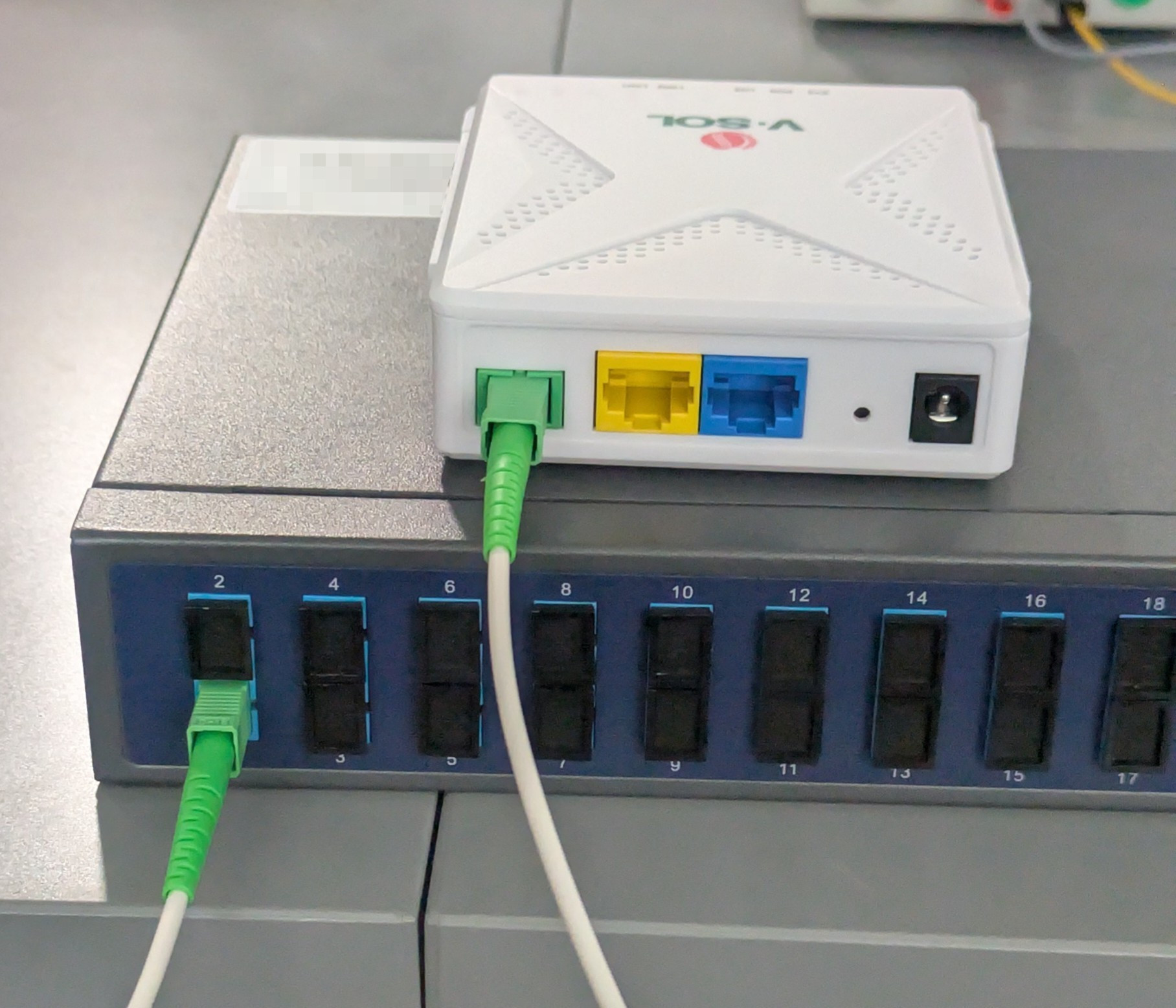
ONU (top) connected to the OLT (bottom) through an optical fibre. The ONU is plugged on one of the passive optical splitter ports, the splitter is integrated with the OLT here.
The Optical Distribution Network: multiplexing optical signals
One key aspect of an Optical Distribution Network (ODN) is that the signal is carried over a reduced number of optical fibres up to a splitter where individual fibres will carry the signal to the end user.
To multiplex signals over a single fibre, several techniques are used depending on the specification or implementer's choice: Wavelength Division Multiplexing (WDM), Time Division Multiplexing (TDM) or combining both using Time and Wavelength Division Multiplexing (TWDM).
WDM uses different light frequencies to carry multiple signals. Due to carefully chosen frequencies, GPON, XG(S)-PON, NG-PON2 and 50G-PON can coexist on the ODN using a coexistence element (see ITU-T G.980519). For NG-PON2 and HSP, WDM is also used to increase the overall bandwidth by creating several channels that each use a different frequency pair. WDM can also designate the separation of transmit/receive frequencies to use on a single fibre, as opposed to using an individual fibre for each direction.
Taking GPON as an example, the downstream signal is carried on a single fibre from the OLT up to a passive splitter. WDM is used: the upstream and downstream signals use separate wavelengths. The signal is then split (copied) between up to 128 users in the last kilometre and carried using individual fibres. Instead of running 128 individual fibres over up to 60km, only the last few metres will require individual fibres, which reduces the cost and complexity. However, this also means that all 128 users on the same ODN will receive the same downstream signal containing all users' data.

Downstream PON
As for the upstream signal, it uses Time Division Multiple Access (TDMA), a specific type of TDM: each ONU sends bursts on a timing provided by the OLT, which enables all the individual optical signals from the ONUs to be passively aggregated again before reaching the OLT.

Upstream PON
For HSP and NG-PON2, the combination of WDM and TDM to create channels is designated as TWDM.
The impact of PON architecture on security
As the downstream signal is passively split between all the ONUs, they all receive the same downstream signal which contains their data but also their neighbours'. Basically, all downstream communications are broadcast at the link level, which mandates specific security measures.
As for the upstream signal, it is not carried to other users. However, it can still be intercepted on each individual fibre or when aggregated by the combiner en route to the OLT.
In both cases, authentication and encryption are desirable to avoid eavesdropping, tampering, or man-in-the-middle attacks, which brings us to the threat model of PON specifications.
The PON's protocol stack
In the previous sections, we learned how PONs are structured. This section presents the protocols used to configure the PON link and how data is framed. The objective is to present a condensed view of the frame structure; it can be glossed over and used as a reference for the next security-focused part.
Three main configuration channels: Embedded OAM, PLOAM and OMCI
Before going into the frame structures, let us mention three protocols used by GPON, XG(S)-PON, NG-PON2 and 50G-PON:
- Embedded layer Operation, Administration and Maintenance (Embedded OAM): fields embedded in the frame headers for low latency access, for instance, the frame identifier or the upstream bandwidth allocation.
- Physical layer Operation, Administration and Maintenance (PLOAM): used for other information not sent by the above that relates to the link layer, information that is less time-sensitive but used to configure the connection. For instance, sending the serial number to the OLT, the ONU ID, sending the data encryption key, etc.
- ONU Management and Control Interface (OMCI): the protocol used for high-level configuration of the ONU (the channel is actually called ONU Management and Control Channel (OMCC)). The protocol is defined in the ITU-T G.988 ONU management and control interface (OMCI) specification 15. It uses a Management Information Base (MIB) synchronised between the ONU and the OLT, and allows complex mutual authentication, Layer 2 and Layer 3 configuration, ONU debug, etc.
Four layers
GPON, XG(S)-PON, NG-PON2 and 50G-PON all have similar frame structures, sharing a few similar characteristics:
- When TDM is used (which is most of the time), the upstream frame structure is slightly different from the downstream frame structure.
- The frames have four layers: Physical Medium Dependent (PMD) layer, Transmission Convergence (TC) PHY Adaptation Sublayer, TC Framing Sublayer (FS) and TC Service Adaptation Sublayer.
- The lower layer is the PMD layer, which defines how data is encoded on the optical line.
- The layer between the PMD and user functionalities (Service Data Units, SDUs) is the TC layer. It's called GTC for GPON4, XGTC for XG-PON9, XGS-PON TC10 for XGS-PON, TWDM TC for NG-PON214 and ComTC (for Common TC) for 50G-PON (HSP)17. 50G-PON/Higher Speed PON generalises the TC layer from XG-PON onwards.
- The TC service adaptation sublayer contains (X)GEM frames ((10) Gigabit PON Encapsulation Method) which encapsulate the actual data payload (Ethernet frames for instance).
The diagram below represents a downstream frame and its separation into different layers. This representation deliberately shows only a few fields which are relevant to explain how PON works or are security-related. Technically, it only applies to XG(S)-PON, NG-PON2 and 50G-PON, but GPON is similar. Moreover, while the name and overall purpose of a field might be the same between PON versions, the structure can differ.

XG(S)-PON, NG-PON2 and 50G-PON downstream frame structure
The fields shown on the diagram have the following use:
- Superframe counter (SFC): 51-bit (XG(S)-PON, NG-PON2 and 50G-PON), 30-bit (GPON), wraps around to 0. It is used in the data encryption process for the counter mode of operation.
- PLOAMd: used by the OLT in the PLOAM configuration protocol, for instance to request a new data encryption key.
- BWmap: not directly security-related, but contains the timings on which upstream frames can be sent for each ONU (for TDMA). More precisely, the OLT assigns Allocation IDs (Alloc-IDs) to the ONUs (a default one is always assigned for OMCI). These Alloc-IDs are then associated with Transmission Containers (T-CONs) which represent a group of logical connections which can be assigned a bandwidth. Finally, each downstream frame contains the bandwidth assignment for the Alloc-IDs, which means each Alloc-ID/T-CON will have a dedicated time to send an upstream burst. Note that the TC layer is only concerned with Alloc-IDs, T-CONs are managed through OMCI and another structure could map to Alloc-IDs. T-CONs are then mapped to (X)GEM ports, the smallest connection entity. Grouping (X)GEM ports into T-CON enables managing bandwidth for QoS (Quality-of-Service) purposes, to prioritise real-time signals such as voice audio.
- Encryption key index: only for XG(S)-PON, NG-PON2 and 50G-PON. Indicates if the downstream payload is: unencrypted, encrypted using key 1, encrypted using key 2 (key index relative to the key slot). GPON does not have such a field: the OLT does not select a key slot but sends a Superframe counter value to the ONU through PLOAMd at which the new key (to be sent) will be used.
In GPON, the FS Header and PSBd are actually merged as a single header (named GTC Header or PCBd) with a similar purpose. Another difference is that while the PLOAMd, BWmap and SFC fields are present in all PON versions, the Encryption key index is only present in XG(S)-PON, NG-PON2 and 50G-PON.
The diagram below represents an upstream frame for XG(S)-PON, NG-PON2 and 50G-PON; it differs slightly for GPON, but it is overall very similar:

XG(S)-PON, NG-PON2 and 50G-PON upstream frame structure
The upstream frames are sent in bursts. Each Alloc-ID is given an opportunity to send data according to the BWMap field sent in the downstream frame. Alloc-ID bandwidth allocations that belong to the same ONU and are consecutive (in time and thus in the BWMap) are called an allocation series. They start with an FS Header and end with an FS Trailer.
Threat models of GPON, XG(S)-PON, NG-PON2 and 50G-PON
All the ITU-T PON specifications referenced have a threat model, which has greatly improved from GPON to XG-PON. XGS-PON/NG-PON2/50G-PON share the XG-PON threat model for the most part.
The GPON4 threat model can be summarised as such:
- An attacker or user having reprogrammed an ONU, or having otherwise access to the incoming optical signal, can access all downstream communications including data from all the other OLT users.
- Other threats such as eavesdropping on the upstream link are considered impractical because the attacker would have to tap into the fibre, sometimes in public places and in a noticeable way for the PON.
The XG-PON specification9 as well as XGS-PON9 10, NG-PON214 and 50G-PON17 have gone back on this model, taking upstream threats into account as well:
- An attacker or user having reprogrammed an ONU, or having otherwise access to the incoming optical signal, can access all downstream communications including data from all the other OLT users.
- An attacker or user having reprogrammed an ONU can impersonate another ONU and forge packets.
- An attacker could intercept or generate traffic at any point on the ODN (which sometimes spans 60 km) between the OLT and the ONU, impersonating the OLT or an ONU.
- An attacker or user could use any of the scenarios above to record and replay packets transmitted on the PON, or modify the packets (bitflips for instance).
Overall, the threat model has improved significantly since GPON, considering security issues in both directions (OLT to ONU and ONU to OLT), as well as eavesdropping anywhere between the OLT and ONUs. This translates into improved security features as well.
Additionally, a study group with members from China Telecommunications Corporation, Verizon, Huawei Technologies Co., Ltd. and ZTE Corporation has published recommendations named "Practical aspects of PON security" starting from 2022. A first supplement has been published20, with the objective “to guide the security experts on operators’ expectations about the security of their access networks and on the criteria of a valuable security proposal, as well as the reference to the operators on configuring their networks to achieve the best possible security performance.”.
The improved threat model in the supplement separates the threats into several categories:
- Eavesdropping: downstream and upstream.
- Theft of service: unauthorised access to the PON.
- Denial of service.
- Theft of data.
- Impersonation.
- Disruption of operations: disruption from a single ODN to a larger scale (entire ISP for instance).
The supplement insists that “regardless of how strong the link-level encryption strength is, no end-to-end data security property can be derived from it”. Indeed, PON specifications are only concerned with establishing a secure channel between an ONU and an OLT, at the link level. This channel is not established between an end user and a service provider directly.
Overall, the supplement gives more context to the threat model and makes recommendations on key management and handling of ONU identifier duplication. The XG-PON ITU-T G.987.39, NG-PON2 ITU-T G.989.314 and 50G-PON ITU-T G.9804.217 specifications' latest amendments actually recommend using this supplement for best practices related to key management. As it is recommended by the specifications, it probably must be implemented.
One threat that does not seem to be mentioned in any of the threat models is the exploitation of vulnerabilities in the OMCI Management Entities, which have a large attack surface. The implementation of the OMCI Management Entities functionalities is down to the manufacturer so this might be outside the specification perimeter however.
PON security measures
Authentication and cryptographic schemes
Authentication in ITU-T PONs can be surprisingly complex, as there are multiple identifiers and schemes available. They are sometimes combined, and the authentication methods do not all ensure the same level of security.
We will separate the use of these identifiers into two categories:
- Identification: the OLT requests an identifier, but there is no secure channel bound to this identifier. In GPON, the OLT can request an identifier and then request an encryption key, but the key is not bound to the identifier, which is why only one authentication scheme is considered for GPON (OMCI-based).
- Authentication: the OLT (and the ONU if the authentication is symmetric) uses a cryptographic scheme to authenticate its counterpart. The results of this authentication can be used to establish a secure channel between the two devices. Keep in mind that, as we'll see in the next sections, a successful authentication does not mean the secure channel is activated, only that it can be.
All PON versions start with an identification step: at the very start of its connection to the OLT, the ONU sends its serial number.
Then, for GPON, cryptographic authentication is entirely optional. For XG-PON and later, a Registration ID-based authentication will always be performed after ONU initialis ation, whether Registration_ID is the default null string or a provisioned one. If a Registration_ID is not provisioned, it will not provide meaningful authentication.
After the mandatory identification or authentication steps, the OLT can start a new authentication process at any point, or request other identifiers. For authentication, up to three cryptographic schemes are available depending on the PON version. Some of these schemes allow for mutual authentication (ONU to OLT, but also OLT to ONU), all of them lead to the creation of a Master Session Key (MSK) which can then be used to establish a secure channel.

Authentication decision diagram
The Logical ONU ID (LOID) / LOID password identifiers often present in ONU web interfaces can be a bit confusing. They seem to be both implemented in custom OMCI Management Entities (as is the case for the Management Entity 65530 used by Huawei ONUs) and in the standard "ONU-G" OMCI Management Entity. The O3 Labs website21 lists several vendor-specific OMCI Management Entities.
Note that a combination of these identifiers and schemes can be used at different steps during the configuration of the ONU. For an XGS-PON link the following sequence could be used:
- Identify the ONU through the serial number sent at the start of the link initialisation.
- Request the Registration ID from the ONU, derive an MSK using the corresponding cryptographic scheme and enable encryption.
- Start the OMCI cryptographic scheme and transition to the new MSK.
The (mutual) secure authentication mechanisms
In the previous section, we mentioned three authentication mechanisms based on cryptography: Registration ID-based, OMCI-based and IEEE 802.1X-based.
Only the last two are mutual authentication schemes that authenticate both the ONU and the OLT.
Registration ID-based authentication
Only available in XG(S)-PON, NG-PON2 and 50G-PON. This is the default authentication mode based on a 36-byte value called Registration_ID and it is not mutual. The Registration_ID is requested by the OLT during the ONU activation process and can be queried at any time through a PLOAM message, which is unencrypted.
This mechanism is thus vulnerable to several threats, for instance:
- An attacker can unplug the target optical fibre, plug it in their OLT, request the Registration_ID, derive the keys and use them to decrypt the encrypted data encryption key transmitted through PLOAM after the device has been plugged back to the original OLT.
- An attacker could tap at any point between the targeted user and the OLT and see the Registration_ID in clear form, derive the keys and use them to decrypt the encrypted data encryption key transmitted through PLOAM.
The Registration_ID is not meant to be changed regularly, the attacker can query it once and reuse it at any time. Moreover, if it is unchanged, the default is used.
A key consideration is that has a default value , which will be used for the Registration ID-based authentication unless a Registration_ID has been provisioned. Thus, the specifications effectively allow the use of one of the cryptographic authentication schemes with a known (weak) secret. Having the possibility to use an unauthenticated/unencrypted channel, which would not provide a false sense of security, would seem preferable.
Registration ID-based MSK derivation
Let:
- be the 36-byte Registration ID.
- be the required MSK length.
- be the 128-bit AES key used in the AES-ECMAC definition.
- be the input message used in the AES-ECMAC definition.
- be the requested MAC output length in bits.
- be the with its final 16 octets removed.
is derived the following way:
where
OMCI-based authentication
This is one of the two mutual secure authentication mechanisms, now defined in ITU-T G.98815 (originated in ITU-T G.984.45 for GPON). The scheme assumes a Pre-Shared Key () has been provisioned on both the ONU and OLT beforehand.
A three-step challenge-based mutual authentication is used:
Three-step OMCI authentication
- The OLT sends its list of supported MAC (Message Authentication Code) functions and to the ONU.
- Then, the ONU selects one of the supported OLT MAC functions, then sends the and the following MAC to the OLT:
- Finally, OLT then sends a MAC to the ONU as well:
The OLT advertises its supported in the "OLT crypto capabilities" attribute of the OMCI "Enhanced security control" Management Entity. Then, the ONU chooses one of these and sets the "ONU selected crypto capabilities" attribute of the OMCI "Enhanced security control" Management Entity. It is then used as .
is chosen from the following list:
- AES-CMAC-128 (default, must be supported).
- HMAC-SHA-256.
- HMAC-SHA-512.
Master Session Key derivation
Finally, the is derived from the and the challenges. The following formula is used when a 128-bit is required, which is always the case for GPON, XG(S)-PON and NG-PON2:
OMCI-based 128-bit derivation
However, 50G-PON also supports 256-bit MSKs. When combining the ITU-T G.988 (OMCI)15 and ITU-T G.9804.2 (50G-PON)17 specifications, it is unclear how should be derived in this situation. ITU-T G.9804.2 also defers to ITU-T G.987.39 for OMCI authentication.
When , the equation is clear:
OMCI-based 50G-PON 256-bit MSK derivation for
where
When or are used, the specifications imply one of two things:
- Following ITU-T G.9804.2 Annex C “Secure mutual authentication”, the output of is truncated to 256 bits, as generates a 256-bit value and a 512-bit value.
- ITU-T G.988 requires to be truncated to 128 bits. According to ITU-T G.9804.2 clause 9.13, must be extended to 256 bits using the same process as the "OMCI-based 50G-PON 256-bit MSK derivation for " equation above.
The key contradictory quotes are available in Annex C: Contradictory specification quotes relative to the derivation of a 256-bit for HMACs with an output size of 256-bit or more.
As both the ONU and OLT must derive the same , a manufacturer testing this specific case with different ONUs or OLTs would notice any implementation mismatch. A clarification of the specification would make clear what is actually implemented, but all manufacturers should have the same implementation eventually. As 50G-PON is not widely deployed, they might not have faced this choice yet, especially with these specific .
IEEE 802.1X-based authentication
This is the second mutual secure authentication mechanism, only available in XG(S)-PON, NG-PON2 and 50G-PON. Its implementation is mostly detailed in Annex D of ITU-T G.987.39.
IEEE 802.1X supports many authentication methods through the Extensible Authentication Protocol (EAP)23. EAP-GPSK24 which is based around a pre-shared key, must be supported according to ITU-T G.987.39. EAP-TLS25 is also mentioned in the specification and allows the use of public-key cryptography. Any EAP method that supports mutual authentication and the generation of a secret can be used.
RFC 374823 mentions that the generated must be at least 64 bytes long, however we need only 16 bytes or 32 bytes (50G-PON only).
IEEE 802.1X-based MSK derivation
Let be the required size in bits. is derived from as follows:
A note on Forward Secrecy
Only one authentication scheme, the IEEE 802.1X-based scheme with the right EAP (EAP-TLS with a Diffie-Hellman key exchange for instance), might lead to an encrypted session that provides perfect forward secrecy. For the other schemes, the leak of the Registration_ID or PSK would enable attackers to decrypt the signal in harvest now, decrypt later attacks. The encrypted data encryption key contained in the PLOAM messages could be decrypted, and then the payloads of the XGEM frames.
Key Derivation
and its derived keys have three purposes: encrypting the data encryption key (using the for GPON or the Key Encryption Key () otherwise), authenticating PLOAM messages and authenticating OMCI messages (XG-PON and above only).

Key derivation decision diagram
Note that the typos and wordplays in the strings match the actual values used by the specifications, as specific string lengths were required.
XG(S)-PON and NG-PON2 derivations
50G-PON derivations
Let:
- be the key used in the BC-ECMAC definition.
- be the input message used in the BC-ECMAC definition.
- be the requested MAC output length in bits.
- be the chosen Block Cipher.
- be with its final 16 octets removed.
where
For GPON, the data encryption key is only sent encrypted when the OMCI authentication is used; otherwise it is sent in clear form. The key is always sent encrypted in XG(S)-PON, NG-PON2 and 50G-PON, using the key derived from the MSK.
The other two keys derived from the MSK in XG(S)-PON, NG-PON2 and 50G-PON are used for the authentication of OMCI and PLOAM messages, so only OMCI and PLOAM have authenticity checks, not the main payload. GPON does not have such a mechanism.
Authentication of PLOAM and OMCI messages
Only XG(S)-PON, NG-PON2 and 50G-PON authenticate the PLOAM and OMCI messages; GPON does not. Authentication ensures the messages have been sent by the right peer and that they have not been tampered with.
The PLOAM and OMCI Message Integrity Check (MIC) values are derived the following way:
PLOAM and OMCI MIC calculation
where for downstream and for upstream.
and
is for XG(S)-PON and NG-PON2. For 50G-PON, the chosen block cipher used across data encryption, key derivation and message integrity checks is used for OMCI. This allows 50G-PON to use stronger keys (256-bit). PLOAM, however, always uses .
PLOAM and OMCI authentication is always enabled; however, before any MSK has been derived a default key is used for PLOAM: . The default key is always used for downstream broadcast PLOAM messages, as well as some unicast PLOAM messages such as the Serial_Number_ONU, Deactivate_ONU-ID, Request_Registration and Registration PLOAM messages. After that, the keys derived from the MSK established from the Registration_ID are used, and finally the keys derived from any new MSK established from one of the authentication mechanisms.
Generating the data encryption keys
There are two types of data encryption keys: unicast and multicast (broadcast). In the previous sections, we only mentioned which keys are used to encrypt the unicast data encryption key; not how it is generated.
The unicast data encryption key used in the GPON, XG(S)-PON and NG-PON2 specifications is generated by each ONU, not the OLT.
GPON, XG-PON and NG-PON2 data encryption key generation
A secure random number generator must be used.
Moreover, if the key is not generated properly, all the authentication and key encryption will not matter as the attacker could bruteforce the data encryption key. Thus, according to the XG(S)-PON and NG-PON2 specifications, “the ONU generates a new encryption key using a random number generator suitable for cryptographic purposes”14. The GPON specification has a similar mention “The ONU should generate a cryptographically unpredictable key.”4.
As for 50G-PON, the unicast data encryption key is now derived from both an OLT and an ONU random number, instead of being taken directly from the random number generator output:
50G-PON data encryption key generation
Let:
- be the Key Encryption Key derived from .
- be the chosen Block Cipher.
- be the key size.
- and be values sent to the ONU through PLOAM by the OLT.
- as previously defined.
- be with the ECB cipher mode.
where
and
A secure random number generator must be used.
However, the key is still generated on the ONU side, sent encrypted to the OLT and used as-is. Thus, it seems that the ONU can still hardcode a key or ignore the OLT's contribution, and is responsible for the key strength more generally. But the ONU can now use the OLT entropy pool to increase the data encryption key strength.
Finally, for XG-PON and above, the data encryption key is sent encrypted to the OLT, using the chosen block cipher in ECB mode and as key. For GPON, is used instead of , and encryption of the data encryption key not mandatory.
Encryption of the data encryption key
For GPON
For XG-PON and above
where for XG(S)-PON and NG-PON2.
XG(S)-PON, NG-PON2 and 50G-PON also allow the use of a multicast data encryption key which is generated on the OLT and allows a frame to be encrypted once so that it can be decrypted by multiple ONUs.
Enabling encryption
Encryption is mostly disabled by default for all PON versions.
For GPON, the encryption of a GEM port is activated through PLOAM, and only the downstream frames are encrypted. For XG-PON and above, the default XGEM port which is used for OMCI is always set for bidirectional unicast encryption, other XGEM ports must be provisioned (unicast/multicast, direction of the encryption, etc). However, the encryption of the frame is still enabled by the Key_index field in the frame header, although the XG-PON specification does mention that it must be done “within the explicitly configured or pre-defined capabilities of the associated XGEM port”.

Enabling encryption decision diagram
For the encryption of the OMCI messages (on the OMCC channel), no OMCI Management Entity needs to be configured. For XG-PON and above, ITU-T G.98815 mentions that “If the GEM frame itself contains an encryption key index, it is understood to refer to the unicast key and to require encryption both up- and downstream.” and the XG(S)-PON and above specifications say “Whenever the default XGEM port traffic is encrypted in the downstream direction, the ONU is expected to encrypt the default XGEM port traffic upstream”. One interpretation of that last quote could imply that an unencrypted frame can be sent to the default (OMCI) XGEM port, which slightly contradicts the ITU-T G.988 specification.
Implementers should make sure that the Key_index value of a specific frame matches the configuration of the XGEM port.
PLOAM messages and OMCI Management Entities relevant to security features
There are a few PLOAM messages and OMCI Management Entities related to security features that are scattered in the specifications. Annex B: PLOAM and OMCI security-related messages can be used as a reference and might be useful for the next section.
Encrypted communications
Finally! We've identified the ONU, passed the authentication process, established an MSK, derived the keys, generated a random data encryption key and sent it encrypted to the OLT, we've enabled the encryption on the (X)GEM port, set the right fields in the (X)GEM header, authenticated the OMCI and PLOAM messages (unless GPON), and at last we can send our encrypted message!
Block cipher and CTR mode
First of all, only the payload of the X(GEM) frame is encrypted, not the X(GEM) header.
The default encryption method is AES-128-CTR (AES-128 with the counter mode of operation specified in NIST SP 800-38A22) and it must be supported by both the ONU and the OLT. In addition to AES-128, 50G-PON (ITU-T G.9804.217) must also support AES-256. However, for 50G-PON, the OMCI "ONU2-G" Management Entity can advertise and enable support for other block ciphers: Camellia-128, Camellia-256 and SM4-128.
While technically, the NIST SP 800-38A22 “assumes that a FIPS-approved symmetric key block cipher algorithm has been chosen as the underlying algorithm”, and Camellia and SM4 are not NIST-approved, the same counter mode is used for all block ciphers.
Even though CTR is a strong encryption mode, it does not provide authentication, which means an attacker can blindly modify the encrypted payload. Other protocols such as TLS 1.3 use AEAD (Authenticated encryption with additional data) modes to provide both encryption and authentication of the main payload, as well as authentication of additional data that must stay visible (a header for instance).
The Counter
The counter is reset at the start of each (X)GEM frame, and its initial value is called Initial Counter Block in XG-PON and later but this designation works for GPON as well. It is then increased by one after each 16-byte block inside the (X)GEM frame.
The Initial Counter Block is a function of the SFC which is sent by the OLT and the Intraframe counter (IFC). The IFC is reset to 0 at the start of each FS frame, increased every 4 bytes for GPON and every 16 bytes for XG-PON and later. The IFC value used in the Initial Counter Block calculation is the IFC value at the first byte of the GEM header for GPON, and at the position of the first four bytes for XG-PON and later (XGEM frames are aligned on a 4-byte boundary).
The figures below represent the SFC, IFC and how (X)GEM frames are encrypted for downstream GPON and XG-PON (and above).

Encryption of a downstream (GPON) GEM frame

Encryption of a downstream XGEM frame
Duplicated counter blocks
The XG-PON specification and above mention two SFC values which lead to duplicated counter blocks in both directions:
- For XG(S)-PON and NG-PON2: and . According to the specifications, the duplicated counter blocks appear for 250μs once every 4000 years. is used, as one of the 51 bits of SFC is dropped before the counter calculation.
- For HSP/50G-PON: and . According to the specification, the duplicated counter blocks appear for 100μs once every 1000 years. is used, as three of the 51 bits of SFC are dropped before the counter calculation.
where represents 's bits x to y (included) in that order.
To mitigate this issue, the specifications recommend initialising SFC to a small value.
As for the upstream payloads, GPON does not encrypt them. For XG-PON and above, upstream frames can be encrypted, when they are the operation is very similar to the encryption of downstream frames.
The main difference is how IFC is calculated: instead of starting at , IFC starts with a value derived from the StartTime at which the upstream burst is sent. This way, IFC is unique for each Alloc-ID.
Reduced data encryption strength: why?
All the ITU-T PON specifications discussed specify the use of data encryption keys with “reduced effective length”.
Instead of generating a 128-bit encryption key, an ONU may generate a key of size bits where is a multiple of 8, filling the remaining most significant bytes with .
can be reported through the OMCI "Enhanced security control" Management Entity and the "Effective key length" attribute, but it is optional.
While this provision was probably in place to support older devices, it is odd that it is still present in newer specifications that require more capable devices.
Bringing it all together: ONU initialisation and key switching
While we have all the bricks to authenticate and encrypt secure channels between ONUs and OLTs, timing is important: some authentication methods are not available right away, keys are renewed regularly (key switching) or must transition from one authentication method to another, etc.
The diagram below presents the key events of an XG-PON ONU from power-up to the establishment of a secure data channel, highlighting the transitions between authentication schemes. Note that this is a "happy path" scenario; it is designed to demonstrate the integration of the security mechanisms discussed in this post rather than provide an exhaustive state-machine analysis of the full specification.
On the left of the diagram are represented the approximate ONU and key management states that are used in state-machines in the specification; not all events are displayed and some are simplified.

XG-PON timeline for power-up to secure channel
The data encryption key should be regularly regenerated by the ONU on the OLT's request; however, the renewal frequency is at the OLT's discretion.
During key renewal, all PON specifications implement measures to ensure only valid keys are used and the link is not left broken. For GPON, the OLT simply sends a superframe counter value to the ONU, at which the new key will be used. For XG-PON and above, the process is more complex and involves timers and state machines. While the XG-PON and later specifications mention two ONU timers (the “ONU key exchange waiting timer” and “Key Ack waiting timer”), the ITU-T Supplement 8120 deprecates them “the ONT-side timers are deprecated”, leaving timeout management to the OLT.
Conclusion
ITU-T PON specifications implement link-level encryption and authentication between OLTs and ONUs to protect against eavesdropping, data theft, and impersonation. However, there are many choices to make and steps to follow, and the specifications do not always have a "secure by default" approach.
GPON, as the oldest PON specification in this blog post, offers the most limited security: downstream-only encryption and optional OMCI-based authentication. Without OMCI authentication, unicast data encryption keys are transmitted unencrypted to the OLT.
XG-PON and newer PON specifications (XGS-PON, NG-PON2, 50G-PON) mandate authentication and support bidirectional encryption. However, the Registration ID-based scheme will use a default null string if not provisioned: while the resulting secure channel will be authenticated and encrypted, it will be based on a known secret, which defeats the purpose of the secure channel. Only the IEEE 801.2X-based scheme with the right EAP mode (such as EAP-TLS with a Diffie-Hellman key exchange) can support Perfect Forward Secrecy (PFS), preventing "harvest now, decrypt later" attacks.
For all PON versions, encryption is usually disabled by default. Only the OMCI XGEM port is always encrypted in both directions for XG-PON and above.
Then, a block cipher (usually AES-128) is used in CTR mode for the actual encryption of the (X)GEM payloads. The CTR mode does not provide authentication of the payload, which means an attacker can blindly modify the ciphertext without being detected. AEAD modes, which are the only modes supported by TLS 1.3 for instance, provide both encryption and authentication of the payload simultaneously.
A somewhat new evolution in the PON specifications is the support of 256-bit block ciphers by the Higher Speed PON (HSP)/50G-PON specifications. 50G-PON now mandates the support of 256-bit keys, and generalises the use of ciphers of this key size. While we do not make any conclusions on the specifications' resilience against quantum cryptography, 256-bit AES keys are recommended by multiple agencies' post-quantum cryptography notes2627 as a measure against Grover's algorithm. ITU-T Supplement 8120 recommends using HMAC-SHA-256 in the OMCI-based authentication scheme for quantum-resistance.
50G-PON also changes how the unicast data encryption key is generated by including an OLT-generated value. However, the key is still generated on the ONU's side and sent to the OLT, unlike a Diffie-Hellman key exchange for instance, where the shared secret is at least guaranteed to include each sides' secret.
Moreover, 50G-PON still includes a section relative to "reduced data encryption strength", which has carried on across PON specifications since GPON. It is unclear why such a provision is still necessary when 256-bit keys have been introduced.
Finally, while we did go through a lot of PON security threats and features, there are other concerns that we did not discuss. The ITU-T specifications and supplements also mention "rogue ONUs", ONUs that do not behave according to the specification, and how to protect against them. Cloned ONUs, attacks against OMCI Management Entities, are other subjects we did not tackle.
Acknowledgments
I would like to thank my colleagues Angèle Bossuat and Célian Glénaz for their review, as well as all other reviewers of this blog post!
Further reading
References
-
R. Rousseau, “Avec le 50G-PON, Orange propose une expérience inédite en France et démontre la prouesse de la fibre du futur,” Newsroom Groupe Orange. Available: https://newsroom.orange.com/?p=60059. ↩
-
ITU-T G.984.1 (03/2008) - Gigabit-capable passive optical networks (GPON): General characteristics ↩
-
ITU-T G.984.2 (08/2019) - Gigabit-capable Passive Optical Networks (G-PON): Physical Media Dependent (PMD) layer specification ↩
-
ITU-T G.984.3 (2014) Amd. 2 (11/2025) - Gigabit-capable passive optical networks (G-PON): Transmission convergence layer specification ↩↩↩
-
ITU-T G.984.4 (02/2008) - Gigabit-capable passive optical networks (G-PON): ONT management and control interface specification ↩
-
ITU-T G.987 (06/2012) - 10-Gigabit-capable passive optical network (XG-PON) systems: Definitions, abbreviations and acronyms ↩
-
ITU-T G.987.1 (2016) Cor. 1 (03/2020) - 10-Gigabit-capable passive optical networks (XG-PON): General requirements ↩
-
ITU-T G.987.2 (2023) Amd. 1 (06/2023) - 10-Gigabit-capable passive optical networks (XG-PON): Physical media dependent (PMD) layer specification ↩
-
ITU-T G.987.3 (05/2025) - 10-Gigabit-capable passive optical networks (XG-PON): Transmission convergence (TC) layer specification ↩↩↩↩↩↩↩
-
ITU-T G.9807.1 (2023) Amd. 1 (05/2025) - 10-Gigabit-capable symmetric passive optical network (XGS-PON) ↩↩
-
ITU-T G.989 (10/2015) - 40-Gigabit-capable passive optical networks (NG-PON2): Definitions, abbreviations and acronyms ↩
-
ITU-T G.989.1 (03/2013) - 40-Gigabit-capable passive optical networks (NG-PON2): General requirements ↩
-
ITU-T G.989.2 (2019) Amd. 1 (10/2020) - 40-Gigabit-capable passive optical networks 2 (NG-PON2): Physical media dependent (PMD) layer specification ↩
-
ITU-T G.989.3 (2021) Amd. 2 (05/2025) - 40-Gigabit-capable passive optical networks (NG-PON2): Transmission convergence layer specification ↩↩↩↩
-
ITU-T G.988 (2022) Amd. 2 (05/2025) - ONU management and control interface (OMCI) specification ↩↩↩↩
-
ITU-T G.9804.1 (2019) Amd. 3 (05/2025): Higher speed passive optical networks - Requirements ↩
-
ITU-T G.9804.2 (2021) Amd. 3 (11/2025): Higher speed passive optical networks - Common transmission convergence layer specification ↩↩↩↩↩
-
ITU-T G.9804.3 (2021) Amd. 3 (02/2026): 50-Gigabit-capable passive optical networks (50G-PON): Physical media dependent (PMD) layer specification ↩
-
ITU-T G.9805 (2022) Amd. 2 (11/2025) : Coexistence of passive optical network systems ↩
-
G Suppl. 81 (ex G Suppl.PONsec) - Practical aspects of PON security - Revision 1 ↩↩↩
-
“GPON - OMCI MIB [O3 Labs].” Available: https://www.tripleoxygen.net/wiki/misc/gpon/omci-mib#privados ↩
-
M. J. Dworkin, “Recommendation for block cipher modes of operation : methods and techniques,” National Institute of Standards and Technology, Gaithersburg, MD, NIST SP 800-38a, 2001. doi: 10.6028/NIST.SP.800-38a. ↩↩
-
J. Vollbrecht, J. D. Carlson, L. Blunk, B. D. Aboba, and H. Levkowetz, “Extensible Authentication Protocol (EAP),” Internet Engineering Task Force, Request for Comments RFC 3748, Jun. 2004. doi: 10.17487/RFC3748. ↩↩
-
C. Clancy and H. Tschofenig, “Extensible Authentication Protocol - Generalized Pre-Shared Key (EAP-GPSK) Method,” Internet Engineering Task Force, Request for Comments RFC 5433, Feb. 2009. doi: 10.17487/RFC5433. ↩
-
D. Simon, R. Hurst, and B. D. Aboba, “The EAP-TLS Authentication Protocol,” Internet Engineering Task Force, Request for Comments RFC 5216, Mar. 2008. doi: 10.17487/RFC5216. ↩
-
“ANSSI views on the Post-Quantum Cryptography transition”. Available: https://messervices.cyber.gouv.fr/guides/en-anssi-views-post-quantum-cryptography-transition ↩
-
“Post-Quantum Cryptography: Current state and quantum mitigation | ENISA.”. Available: https://www.enisa.europa.eu/publications/post-quantum-cryptography-current-state-and-quantum-mitigation ↩