Author Fernand Lone Sang
Category Reverse-Engineering
Tags Android, bootloader, IDA, reverse-engineering, 2017
Various Samsung Exynos based smartphones use a proprietary bootloader named SBOOT. It is the case for the Samsung Galaxy S7, Galaxy S6 and Galaxy A3, and probably many more smartphones listed on Samsung Exynos Showcase [1]. I had the opportunity to reverse engineer pieces of this bootloader while assessing various TEE implementations. This article is the first from a series about SBOOT. It recalls some ARMv8 concepts, discusses the methodology I followed and the right and wrong assumptions I made while analyzing this undocumented proprietary blob used on the Samsung Galaxy S6.
Context
Lately, I have been lucky enough to assess and to hunt bugs in several implementations of Trusted Execution Environment (TEE) as my day job. As a side project, I began to dig into more TEE implementations, especially on smartphones I had, for personal use or at work and, coincidentally, they come from the same software editor, namely Trustonic [2], co-founded by ARM, G&D and Gemalto. Being Exynos-based is the only common characteristic between the smartphones I had at hand.
Trustonic's TEE, named <t-base, has evolved from Mobicore, G&D's former TEE. To my knowledge, very little public technical information exists on this TEE or its former version. Analyzing it suddenly became way more challenging and more interesting than I initially thought. Let's focus on Samsung Galaxy S6 and investigate further!
While identifying trusted applications on the file system was the easiest part of the challenge, looking for the TEE OS on Exynos smartphones I analyzed is comparable to looking for a needle in a haystack. Indeed, the dedicated partition storing the image of the TEE OS that you can find on some smartphones (on Qualcomm based SoC for instance), cannot be found. It must be stored somewhere else, probably in the bootloader itself, and it is the reason why I started to reverse engineer SBOOT. This article is the first of a series narrating my journey to the TEE OS. I am going to focus on how to determine Samsung S6 SBOOT's base address and load it in IDA.
ARMv8 Concepts
Before launching IDA Pro, let me recall some fundamentals of ARMv8. I'll introduce here several concepts that might be useful to people new to ARMv8 and already used to ARMv7. For a precise and complete documentation, refer to ARMv8 Programmer's Guide [3]. As I am no ARMv8 expert, feel free to add comments if you see any mistake or needed precision.
Exception Levels
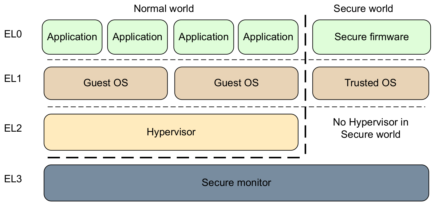
ARMv8 has introduced a new exception model by defining the concept of exception levels. An exception level determines the privilege level (PL0 to PL3) at which software components run and processor modes (non-secure and secure) to run it. Execution at ELn corresponds to privilege PLn and, the greater the n is, the more privileges an execution level has.
Exception Vector Table
When an exception occurs, the processor branches to an exception vector table and runs the corresponding handler. In ARMv8, each exception level has its own exception vector table. For those who are used to reverse engineer ARMv7 bootloaders, you will notice that its format is totally different from ARMv7:
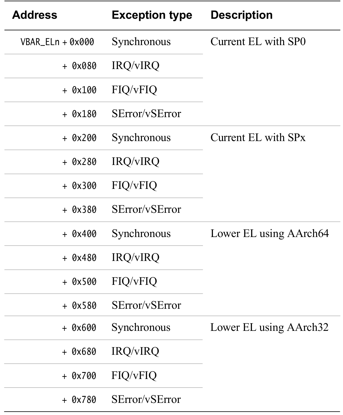
The astute reader may have noticed that entries of the exception vector table are 128 (0x80) bytes long on ARMv8, whereas each entry is only 4 bytes wide on ARMv7, and each entry holds a sequence of exception handling instructions. While the location of the exception vector table is determined by VTOR (Vector Table Offset Register) on ARMv7, ARMv8 uses three VBARs (Vector Based Address Registers) VBAR_EL3, VBAR_EL2 and VBAR_EL1. Note that, for a specific level, the handler (or the table entry) that is going to be executed depends on:
The type of exception (SError, FIQ, IRQ or Synchronous).
If the exception is being taken at the same exception level, the stack pointer to be used (SP0 or SPx).
If the exception is being taken at a lower exception level, the execution state of the next lower level (AArch64 or AArch32).
A software component running at a specific level can interact with software running at the underlying exception levels with dedicated instructions. For instance, a user-mode process (EL0) does a system call handled by the kernel (EL1) by issuing Supervisor Calls (SVC), the kernel can interact with an hypervisor (EL2) with Hypervisor Calls (HVC) or, directly with the secure monitor (EL3) doing Secure Monitor Calls (SMC), etc. These service calls generate synchronous exceptions handled by one of the exception vector table synchronous handlers.
Enough architectural insights for this article, I will write more about this in the upcoming articles. Let us try to load SBOOT into IDA Pro and try to reverse engineer it.
Disassembling SBOOT
To the best of my knowledge, SBOOT uses a proprietary format that is not documented.
Loading SBOOT into IDA Pro
The Samsung Galaxy S6 is powered by 1.5GHz 64-bit octa-core Samsung Exynos 7420 CPU. Recall that ARMv8 processors can run applications built for AArch32 and AArch64. Thus, one can try to load SBOOT as a 32-bit or a 64-bit ARM binary.
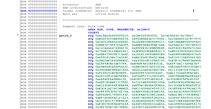
I assumed that the BootROM had not switched to AArch32 state and loaded it first into IDA Pro as a 64-bit binary, leaving the default options:
Processor Type: ARM Little Endian [ARM]
Disassemble as 64-bit code: Yes
Many AArch64 instructions were automatically recognized. When poking around disassembled instructions, basic blocks made sense, letting me think that I really dealt with AArch64 code:
Determining the Base Address
It took me a few days to determine the right base address. As giving you directly the solution is pointless, I first detail all the things I have tried until making the correct assumption which gave me the right base address. As the proverb says, whoever [4] wrote this: "Give a man a fish and you feed him for a day; teach a man to fish and you feed him for a lifetime".
Web Search
I started by searching for Samsung bootloader and SBOOT related work on several search engines. Unfortunately, results on the subject were scarce and only one reverseengineering.stackexchange.com thread [5] dating back to March 2015 was relevant.
This thread mainly gives us 2 hints. J-Cho had the intuition that the bootloader starts at the file offset 0x3F000 and Just helping suggests that it is actually starting at 0x10.
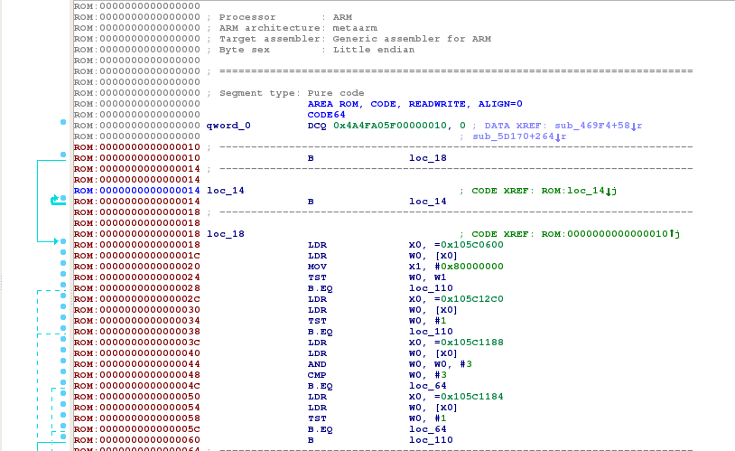
As I wanted to dismiss my hypothesis that the bootloader base address is 0x00000000 and that its code always begins at 0x10, I started to look for bootloaders used in other Exynos smartphones. SBOOT in Meizu's smartphones does not give valid instructions at 0x10, confirming my doubts:
I also analyzed if there were any debug string left on other bootloaders that would give me hints on where SBOOT is generally loaded in memory. No luck :( But I got another lead: some strings in Meizu's SBOOT suggested that U-Boot is used. Even if U-Boot is not used on Samsung Galaxy S6, it was a lead worth exploring and I started to dig further.
U-Boot Repository
U-Boot is open-source and supports several Exynos chips. For instance, Exynos 4 and Exynos 5 have been supported for more than 5 years now. Support for the Exynos 7 has not fully landed on the mainline yet but, based on their mailing list [6], some patches exist for the Exynos 7 ESPRESSO development board.
I may have missed it, but going through patches for the ESPRESSO development board did not bear fruits :( I tried multiple known base addresses from Exynos 4 to Exynos 7 boards without succeeding. It was time to try another angle.
ARM Literal Pools
If you are used to reverse engineering ARM assembly, you must have noticed the massive use of literal pools to hold certain constant values that are to be loaded into registers. This property may help us to find approximately where SBOOT is loaded, especially when a branch destination address is loaded from a literal pool.
I searched all the branching instructions marked with errors in operands (highlighted in red) by IDA Pro. As the code of a bootloader is self-contained, I can safely assume that most of the branches destination address must target code in the bootloader itself. With this assumption, I could approximate the bootloader's base address.
From the very first instructions, I noticed the following branching errors:
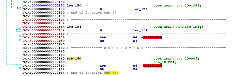
The interesting facts on these code fragments are:
Branching instructions BR (Branch to register) are unconditional and suggest that it will not return.
The operand value for both branches is the same (0x2104010) and, it is located very early in the bootloader.
The last byte is 0x10 which is exactly the offset where the code of the bootloader seems to begin.
I arbitrarily assumed that the address 0x2104010 was a reset address and I tried to load the SBOOT binary at 0x2104000, with the following options:
Processor Type: ARM Little Endian [ARM]
Start ROM Address: 0x2104000
Loading Address: 0x2104000
Disassemble as 64-bit code: Yes
At least, IDA Pro found fewer errors which indicates that my assumption may be correct. Yet, I could not tell for sure that this base address was the right one, I needed to reverse engineer further to be sure. Spoiler: I nearly got it right :)
ARM System Registers
Now that I may have the potential base address, I continued reverse engineering SBOOT hoping that there were no anomalies in the code flow.
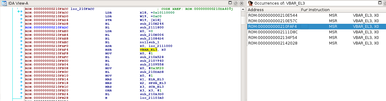
As I wanted to find the TEE OS, I started searching for pieces of code executed in the secure monitor. A rather simple technique to find the secure monitor consists in looking for instructions that set or read registers that can only be accessed from the secure monitor. As previously mentioned, the secure monitor runs in EL3. VBAR_EL3 is rather a good candidate to find EL3 code as it holds the base address of the EL3 exception vector table and leads to SMC handlers.
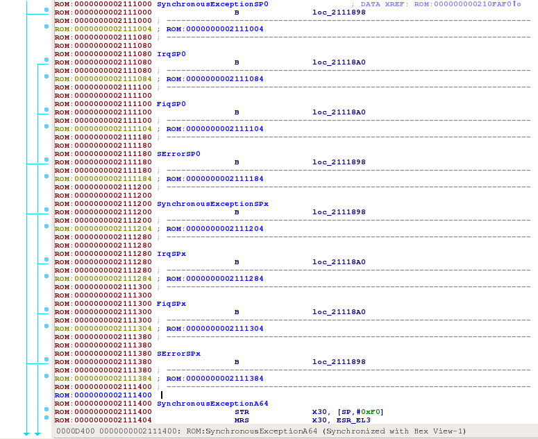
Do you remember the exception vector table's format presented at the beginning of this article? It is made of 16 entries of 0x80 bytes holding the code of exception handlers. Amongst the search results, code at 0x2111000 seemed to lead to a valid exception vector table:
Even though, the chosen base address was still not the right one :( When verifying other instructions that set VBAR_EL3, one can note that 0x210F000 is in the middle of a function:
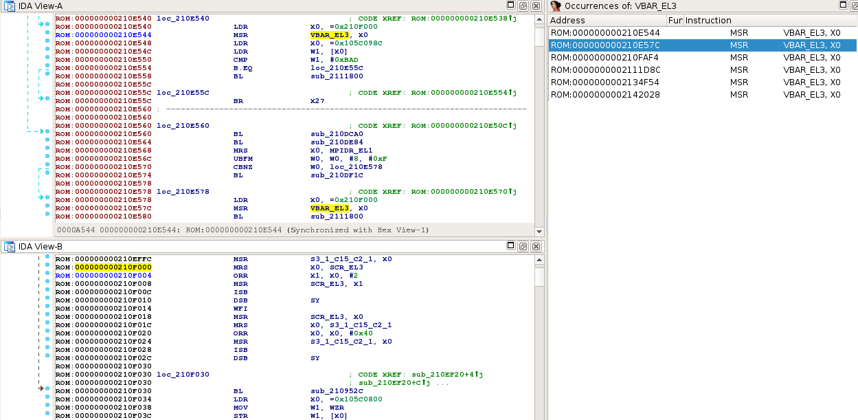
These anomalies would suggest that 0x2104000 is not the right base address yet. Let us try something else.
Service Descriptors
Samsung Galaxy S6 SBOOT is partly based on ARM Trusted Firmware [7]. ARM Trusted Firmware is open-source and provides a reference implementation of secure world software for ARMv8-A, including a Secure Monitor executing at Exception Level 3 (EL3). The assembly code corresponding to the secure monitor is exactly the same as the one in ARM Trusted Firmware. This is good news because it will buy me some time and save me reverse engineering efforts.
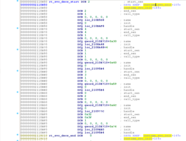
I tried to find another anchor point in the disassembled code I could use to determine the base address of SBOOT. Members of type char * in structures are particularly interesting candidates as they point to strings whose addresses are defined at compile time. While comparing SBOOT disassembled code and ARM Trusted Firmware source code, I identified a structure, rt_svc_desc_t, that had the property I was looking for:
typedef struct rt_svc_desc {
    uint8_t start_oen;
    uint8_t end_oen;
    uint8_t call_type;
    const char *name;
    rt_svc_init_t init;
    rt_svc_handle_t handle;
} rt_svc_desc_t;
According to ARM Trusted Firmware's source code, rt_svc_descs is an array of rt_svc_desc_t that holds the runtime service descriptors exported by services. It is used in the function runtime_svc_init which can be easily located in SBOOT thanks to debug strings in its calling function bl31_main:
I tried to map the binary at different addresses and checked whether I could find valid strings for rt_svc_desc.name entries. Here is a small bruteforcing script:
import sys
import string
import struct

RT_SVC_DESC_FORMAT  = "BBB5xQQQ"
RT_SVC_DESC_SIZE    = struct.calcsize(RT_SVC_DESC_FORMAT)
RT_SVC_DESC_OFFSET  = 0xcb50
RT_SVC_DESC_ENTRIES = (0xcc10 - 0xcb50) / RT_SVC_DESC_SIZE

if len(sys.argv) != 2:
    print("usage: %s <sboot.bin>" % sys.argv[0])
    sys.exit(1)

sboot_file = open(sys.argv[1], "rb")
sboot_data = sboot_file.read()

rt_svc_desc = []
for idx in range(RT_SVC_DESC_ENTRIES):
    start = RT_SVC_DESC_OFFSET + (idx << 5)
    desc = struct.unpack(RT_SVC_DESC_FORMAT,
                         sboot_data[start:start+RT_SVC_DESC_SIZE])
    rt_svc_desc.append(desc)

strlen = lambda x: 1 + strlen(x[1:]) if x and x[0] in string.printable else 0

for base_addr in range(0x2100000, 0x21fffff, 0x1000):
    names = []
    print("[+] testing base address %08x" % base_addr)
    for desc in rt_svc_desc:
        offset = desc[3] - base_addr
        if offset < 0:
            sys.exit(0)
        name_len = strlen(sboot_data[offset:])
        if not name_len:
            break
        names.append(sboot_data[offset:offset+name_len])
    if len(names) == RT_SVC_DESC_ENTRIES:
        print("[!] w00t!!! base address is %08x" % base_addr)
        print("    found names: %s" % ", ".join(names))
Running this script on the analyzed SBOOT gave the following output:
$ python bf_sboot.py sboot.bin
[+] testing base address 02100000
[+] testing base address 02101000
[+] testing base address 02102000
[!] w00t!!! base address is 02102000
    found names: mon_smc, std_svc, tbase_dummy_sip_fastcall,
                 tbase_oem_fastcall, tbase_smc, tbase_fastcall
[...]
Victory! Samsung Galaxy S6 SBOOT's base address is 0x02102000. Reloading the binary into IDA Pro with this base address seems to correct all the oddities in the disassembled code I have seen so far. We are sure to have the right one now!
Enhancing the Disassembly
The reverse engineering process is like solving a puzzle. One tries to understand how a piece of software works by putting back together bits of information. Thus, the more information you have, the easier the puzzle solving is. Here are some tips that helped me before and after finding the right base address.
Missed Functions
While IDA Pro does an excellent job in disassembling common file formats, it will likely miss a lot of functions when reversing unknown binaries. In this situation, a common habit is to write a script looking for prologue instructions and declaring that a function exists at these spots. A simple AArch64 function prologue looks like this:
// AArch64 PCS assigns the frame pointer to x29
sub     sp, sp, #0x10
stp     x29, x30, [sp]
mov     x29, sp
The instruction mov x29, sp is a rather reliable marker for AArch64 prologues. The idea to find the beginning of the function is to search for this marker and to disassemble backward while common prologue instructions (mov, stp, sub for instance) are found. A function that searches for AArch64 prologues looks like this in IDA Python:
import idaapi

def find_sig(segment, sig, callback):
    seg = idaapi.get_segm_by_name(segment)
    if not seg:
        return
    ea, maxea = seg.startEA, seg.endEA
    while ea != idaapi.BADADDR:
        ea = idaapi.find_binary(ea, maxea, sig, 16, idaapi.SEARCH_DOWN)
        if ea != idaapi.BADADDR:
            callback(ea)
            ea += 4

def is_prologue_insn(ea):
    idaapi.decode_insn(ea)
    return idaapi.cmd.itype in [idaapi.ARM_stp, idaapi.ARM_mov, idaapi.ARM_sub]

def callback(ea):
    flags = idaapi.getFlags(ea)
    if idaapi.isUnknown(flags):
        while ea != idaapi.BADADDR:
            if is_prologue_insn(ea - 4):
                ea -= 4
            else:
                print("[*] New function discovered at %#lx" % (ea))
                idaapi.add_func(ea, idaapi.BADADDR)
                break
    if idaapi.isData(flags):
        print("[!] %#lx needs manual review" % (ea))

mov_x29_sp = "fd 03 00 91"
find_sig("ROM", mov_x29_sp, callback)
ARM64 IDA Plugins
AArch64 mov simplifier
Compilers sometimes optimize code, making it harder to read for a human. Using IDA Pro's API, one can write an architecture-specific code simplifier. I found the AArch64 code simplifier shared by @xerub quite useful. Here is an example of AArch64 disassembly:
ROM:0000000002104200                 BL              sub_2104468
ROM:0000000002104204                 MOV             X19, #0x814
ROM:0000000002104208                 MOVK            X19, #0x105C,LSL#16
ROM:000000000210420C                 MOV             X0, X19
@xerub's "AArch64 mov simplifier" [8] changes the disassembly as follows:
ROM:0000000002104200                 BL              sub_2104468
ROM:0000000002104204                 MOVE            X19, #0x105C0814
ROM:000000000210420C                 MOV             X0, X19
Astute readers will probably notice that MOVE isn't a valid ARM64 instruction. MOVE is simply a marker to tell the reverse engineer that current instructions have been simplified and substituted by this instruction.
FRIEND
Reverse engineering ARM low-level code in IDA Pro has always been tedious. Figuring out what an instruction related to the system control coprocessor does is a horrible experience as IDA Pro disassembles the instruction without register aliasing. If you had the choice, which one would you prefer to read:
msr vbar_el3, x0
or
msr #6, c12, c0, #0, x0
ARM helper plugins help in improving IDA Pro's disassembly. IDA AArch64 Helper Plugin [9] by Stefan Esser (@i0n1c) is such a plugin. Unfortunately, it is not publicly available. Alex Hude (@getorix) wrote a similar plugin, FRIEND [10], for MacOS. If you closely followed the project, I recently pushed modifications [11], that had been merged last week, to make it cross-platform. Now, you have FRIENDs for Windows, Linux, and MacOS :)
Signatures
As previously mentioned, SBOOT is partly based on ARM Trusted Firmware [12]. Since the source code is available, one can save a lot of reverse engineering efforts by browsing the source code, recompiling it and do binary diffing (or signature matching) in order to recover as much symbols as possible.
I generally combine multiple binary diffing tools to propagate symbols between binaries:
Bindiff [14] from Zymanics
They sometimes have complementary results.
Conclusion
In this article, I described how to determine SBOOT's base address for the Samsung Galaxy S6 and how to load it into IDA Pro. The method described here should be applicable to other Samsung's smartphones and probably to other manufacturers' products using an Exynos SoC.
The journey to the TEE OS will continue in the next article. Stay tuned folks!
References
| [1] | http://www.samsung.com/semiconductor/minisite/Exynos/w/showcase/smartphones/ |
| [2] | https://www.trustonic.com/about-trustonic |
| [3] | http://infocenter.arm.com/help/topic/com.arm.doc.den0024a/DEN0024A_v8_architecture_PG.pdf |
| [4] | http://quoteinvestigator.com/2015/08/28/fish/ |
| [5] | http://reverseengineering.stackexchange.com/questions/10995/problem-with-ida-pro-6-8-disassemble-galaxy-s6-sboot |
| [6] | http://lists.denx.de/mailman/listinfo/u-boot |
| [7] | https://github.com/ARM-software/arm-trusted-firmware |
| [8] | https://gist.github.com/xerub/c6936d219db8e6635d25 |
| [9] | https://youtu.be/dg6byIiAwtc |
| [10] | https://github.com/alexhude/FRIEND |
| [11] | https://github.com/alexhude/FRIEND/pull/6 |
| [12] | https://github.com/ARM-software/arm-trusted-firmware |
| [13] | https://github.com/devttys0/ida/blob/master/plugins/rizzo/rizzo.py |
| [14] | https://www.zynamics.com/software.html |
| [15] | https://github.com/joxeankoret/diaphora |
Acknowledgements
jb for all the discussions we had and for his help.
André "sh4ka" Moulu for encouraging me to write this series of articles, describing my journey to the TEE OS.
Quarkslab colleagues for their feedback on this article.