Authors Philippe Azalbert, Alexandre Chazal
Category Automotive
Tags hardware, reverse-engineering, file formats, emulation, ARM, 2024
This blogpost explains how we recovered the firmware of a fleet-sharing Electronic Control Unit (ECU) which has been erased from a FAT memory using Capstone disassembler to locate scattered parts, to be able to reverse-engineer it.
Introduction
We were asked to conduct a black-box assessment of a fleet-sharing Electronic Control Unit (ECU) to evaluate if an attacker could be able to intercept and alter ciphered commands sent over BLE that could lead to an unauthorized access to the vehicle.
Dump all the things
The first step in this kind of assessment is to conduct a hardware analysis of the device to identify the main chips and dump the firmware.
In our case, the core of the ECU was an ARM-based microcontroller, an STM32F7 connected to a CAN transceiver and dedicated modules for the BLE and LTE connectivity. Additional SDRAM chips and an eMMC were also present.
Debug pins were exposed near the STM32F7 chip, allowing us to quickly find the dedicated Single-Wire Debug (SWD) pins. However, we were not able to dump the firmware from this access, as the Readout Protection (RDP) level was set to 1, blocking any access to the Flash Memory.
Various attacks like the cold-boot attack or fault injection were done on STM32F[0-4] chips, but trying to reproduce them on this new target was not possible in the allotted time.
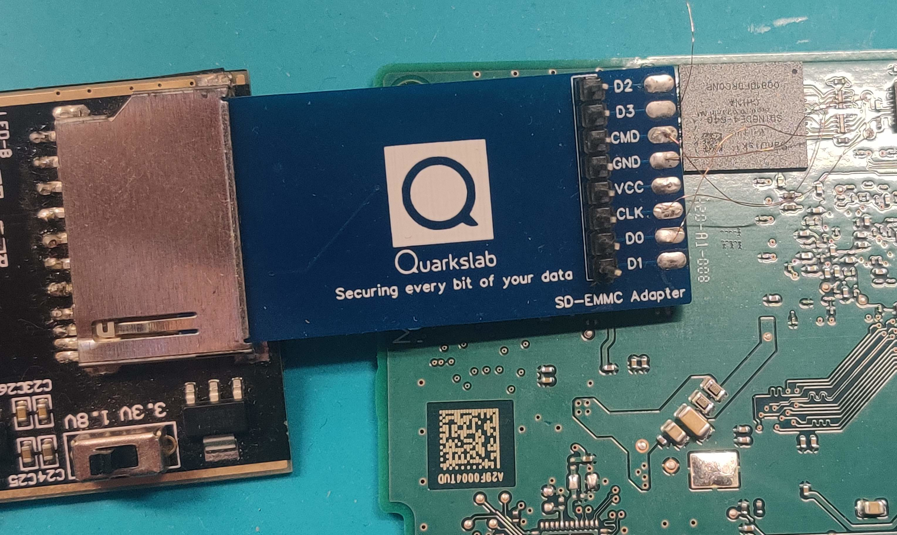
As an eMMC was also present on the PCB, close to the STM32F7, we hoped we could retrieve the firmware by dumping this chip. Having only one ECU for this mission, we decided not to deball the eMMC and tried to find the CMD, CLK, and DAT0 pins. eMMC, which stands for Embedded MultiMedia Card, is similar to a SD card, and connecting those pins to an SD reader allows to mount the memory and dump its content, as well described in the River Loop Security's blog: Hardware Hacking 101: Identifying and Dumping eMMC Flash.
Most of the time, on a device having an eMMC memory, we find a row of resistors close-by that are connected to the DAT[0-7] pins, allowing a quick identification of them. This was not the case for the ECU, as we did not have any exposed pins due to the BGA packages of the STM32F7 and the eMMC. We decided to take pictures of both sides of the PCB, aligned them in GIMP and added an overlay with the pin layout of each chip. Probing vias nearby pins of interest allowed us to find the ones we were looking for. Once done, we soldered the pins we found to an SD adapter using short microwires.
Example on dumping an eMMC by connecting a SD Adapter to pins CMD, CLK, DAT0 and GND.
The last step is to find a way to prevent the MCU from communicating with the eMMC when we will power it. Having debug access using the SWD we started a Telnet server with OpenOCD and issued a halt command to the STM32F7 before connecting our SD card adapter to an SD-card reader, allowing us to dump the content of the eMMC.
Binary analysis
Sadly, this dump was not a quick win, as we were unable to find anything useful using tools like binwalk or unblob.
The file command identified the dump as a DOS/MBR partition:
audit/emmc> fdisk -l user.bin
Disk user.bin: 3.69 GiB, 3959422976 bytes, 7733248 sectors
Units: sectors of 1 * 512 = 512 bytes
Sector size (logical/physical): 512 bytes / 512 bytes
I/O size (minimum/optimal): 512 bytes / 512 bytes
Disklabel type: dos
Disk identifier: 0x00000000

Device     Boot   Start     End Sectors   Size Id Type
user.bin1  *        252  322267  322016 157.2M  6 FAT16
user.bin2  *     322268 1999547 1677280   819M  6 FAT16
user.bin3  *    1999548 3676827 1677280   819M  6 FAT16
The three partitions were almost empty, having a few log files in a proprietary format and a folder labeled update in the first one.
Furthermore, while using the strings command, we got several results that looked like debug strings or symbols commonly found in an executable. Running a new pass with binwalk, this time using the -A option, we found several ARM opcodes in our dump, confirming our assumption that a firmware was stored on the memory.
Loading the eMMC dump into Ghidra and trying several base addresses gave us a very limited result. Ghidra was able to find and decompile some functions that looked legit, but a lot of calls were not correct, pointing to invalid addresses, like in the middle of an audio file for example.
Looking at several addresses where presumed-valid functions were found showed the related data was stored in the first FAT partition. Maybe we need to go for a more forensic approach to retrieve it.
FAT file system 101
The FAT (File Allocation Table) filesystem was developed in 1977 for MS-DOS and Windows operating systems. It had several evolutions, like FAT16, FAT32, or exFAT to adapt to increasing disk capacities and larger files used on newer devices.
To have a good understanding of how a FAT filesystem works, let's dig into some key concepts.
Sectors and clusters
A FAT filesystem is made of several data blocks, called sectors. Typical sector size is 512 bytes. Each sector is addressed by a sector number, starting at 0.
Sectors are grouped into clusters, the unit used by the filesystem to store data. A file (or directory) will use at least one cluster.
Volume Boot Record
The first sector (#0) on a FAT filesystem is the Volume Boot Record. It contains information on the filesystem like:
- Number of bytes per sector (bytes 11-12);
- Number of sectors per cluster (byte 13);
- Number of FAT copies;
- Number of sectors per FAT;
- Total number of sectors in the filesystem;
- Signature, constant
0x55 0xAA(bytes 510-511).
File Allocation Table
Following the Volume Boot Record is located the File Allocation Table. Each entry corresponds to a cluster and tells if it is used and how, depending on its value. On a FAT16 filesystem, an entry is 16 bits long, allowing the following range to be used:
0x0000: cluster is empty0x0002-0xFFEF: index of the next cluster of the file0xFFF7: bad cluster0xFFF8-0xFFFF: last cluster of the file
Note that values are stored in little endian and the first two clusters (0-1) of the File Allocation are always empty.
So if we have a file which is 3 clusters long, starting at cluster 0x0004, we may have the following entries in the File Allocation Table:
Several File Allocation Tables could be present, this was designed for backup purpose. However, it is quite common that 2 File Allocation Tables are present, and only the first one is used.
Root Directory
Following the File Allocation Tables is the Root Directory. It stores information about files and directories located in the root directory of the file system.
Each file/directory stored in the filesystem is described using 32 bytes, called a Short File Name (SFN) Directory Entry, as follows:
- Bytes 00-07: filename in uppercase without space
- Bytes 08-10: file extension
- Byte 11: file attribute (e.g., 0x10: directory, 0x01: read-only)
- Bytes 14-15: file creation time
- Bytes 16-17: file creation database
- Bytes 26-27: number of the first cluster used
- Bytes 28-31: filesize in bytes
For example, a 36-byte long file called TESTFILE.BIN, with its data being stored in cluster number #15 (0x000F), will produce a Directory Entry as follows.
00000000 | 54 45 53 54  46 49 4c 45  42 49 4E 20  00 00 10 75 | TESTFILEBIN ...u
00000010 | 56 57 00 00  00 00 10 75  56 57 0F 00  24 00 00 00 | fW.....ufW..$..
Note that a directory is recorded the same way as a file, the only difference being the specific file attribute and a filesize of 0x00000000.
When a file/directory is erased, its content is not immediately removed from the filesystem. Instead, the first character of its name is changed to 0xE5, so the system knows it can overwrite the data in the related clusters in a later write action.
To be able to store file/directory with a name longer than 8 bytes and an extended character set, the LFN (Long File Name) format was introduced but is not relevant for this blogpost. Anyway, for backward compatibility, a LFN entry will also have its SFN one.
Data Area
The remaining clusters are located in the Data Area to store all other file or directory entries.
FAT file carving
Based on the previous characteristics shown of the FAT filesystem, two main approaches were available to recover deleted files.
The first one is to look for Directory Entry starting with 0xE5, meaning an erased file that has not yet been overwritten.
The second one is to look into the File Allocation Table for linked entries that are not related to any available Directory Entry.
In our case, both approaches gave no result, even if we were able to find a lot of unmapped clusters that seemed to contain data. So how could we clearly identify chunks of firmware stored in our filesystem?
Prologue to a recovery
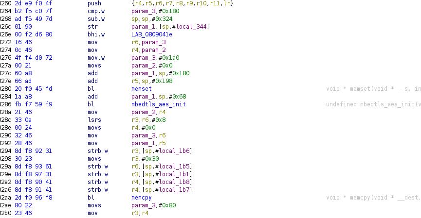
If you have ever reverse-engineered an executable, you must be aware of the prologue and epilogue concepts. To prepare the stack and save previous variables/registers, the compiler generates them for each function.
For the ARM architecture, we have two dedicated instructions to do so, push and pop, that automatically manage the stack pointer. When looking at disassembled code, a function could be resumed as this:
PUSH {registers_x_to_y}
... instructions
POP {registers_x_to_y}
BRANCH offset / link pointer
If two functions are close together, we will have the pop instruction followed by a push one.
Using Capstone-Engine disassembler, we wrote a Python script that loads the dump, reads the Volume Boot Record and checks each cluster in the Root Directory and Data Area to look for the following patterns:
pop-push(consecutive functions)pop-branch(void function return)pop-[ldr/sub/add] r3(function return value)
#!/usr/bin/python3
from capstone import *

SECTOR_SIZE = 512
CLUSTER_SIZE = SECTOR_SIZE * 8
ROOT_DIRECTORY_ADDR = 0x

BASE_ADDR = 0x00200000

def cluster_contains_valid_pattern(cluster_data):
  base_addr = BASE_ADDR
  md = Cs(CS_ARCH_ARM, CS_MODE_THUMB)
  found_pattern = False
  got_pop = False

  for instr in md.disasm(cluster_data,base_addr):
    if "pop" in instr.mnemonic:
      got_pop = True
      prev_mnemonic = instr.mnemonic + " " + instr.op_str
    elif ("push" in instr.mnemonic or "b." in instr.mnemonic or "r3" in instr.op_str) and got_pop == True:
      got_pop = False
      found_pattern = f"{instr.address:#08x} {prev_mnemonic}; {instr.mnemonic} {instr.op_str}"
      break
    else:
      got_pop = False
  return found_pattern
If we find any of them, we assume the cluster contains valid ARM instructions, the probability of random bytes matching such patterns being very low.
$ ./fat_explorer.py --decompile-all
MSWIN4.1 - sector: 512 bytes - cluster: 8 sectors
Start address: 0x0000f800
FAT0: 0x0000fa00 [158 sectors]
FAT1: 0x00023600 [158 sectors]
Root: 0x00037200 [16384 bytes]
Data: 0x0003b200

Decompiling cluster:
--------------------
100%|..........................................| 960/960 [00:40<00:00, 22.98it/s]
Cluster #20:
  0x2008c8 pop {r4, r5, r6, pc}; ldrb.w r3, [sp, #0x19]
Cluster #21:
0x2005fe pop.w {r4, r5, r6, r7, lr}; b.w #0x26d420
Cluster #22:
0x20056c pop.w {r4, r5, r6, lr}; b.w #0x200086
Cluster #24:
0x2001e8 pop {r4, r5, r6, r7}; b.w #0x1ffda4
Cluster #26:
0x200702 pop.w {r3, r4, r5, lr}; b.w #0x267920
Cluster #27:
0x200200 pop.w {r4, r5, r6, r7, r8, sb, sl, fp, pc}; sub.w r3, r3, #0xf00000
[...]
However this approach has two drawbacks:
- We will miss clusters containing no function, like large arrays of struct;
- Clusters are scattered over the filesystem, how can we arrange them in the correct order and know their distances?
From branch to branch
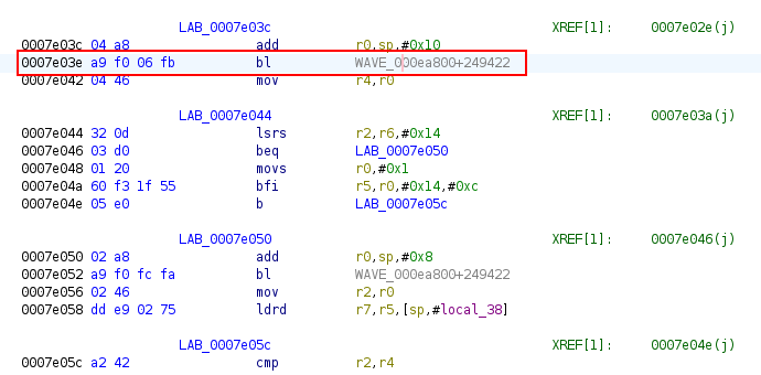
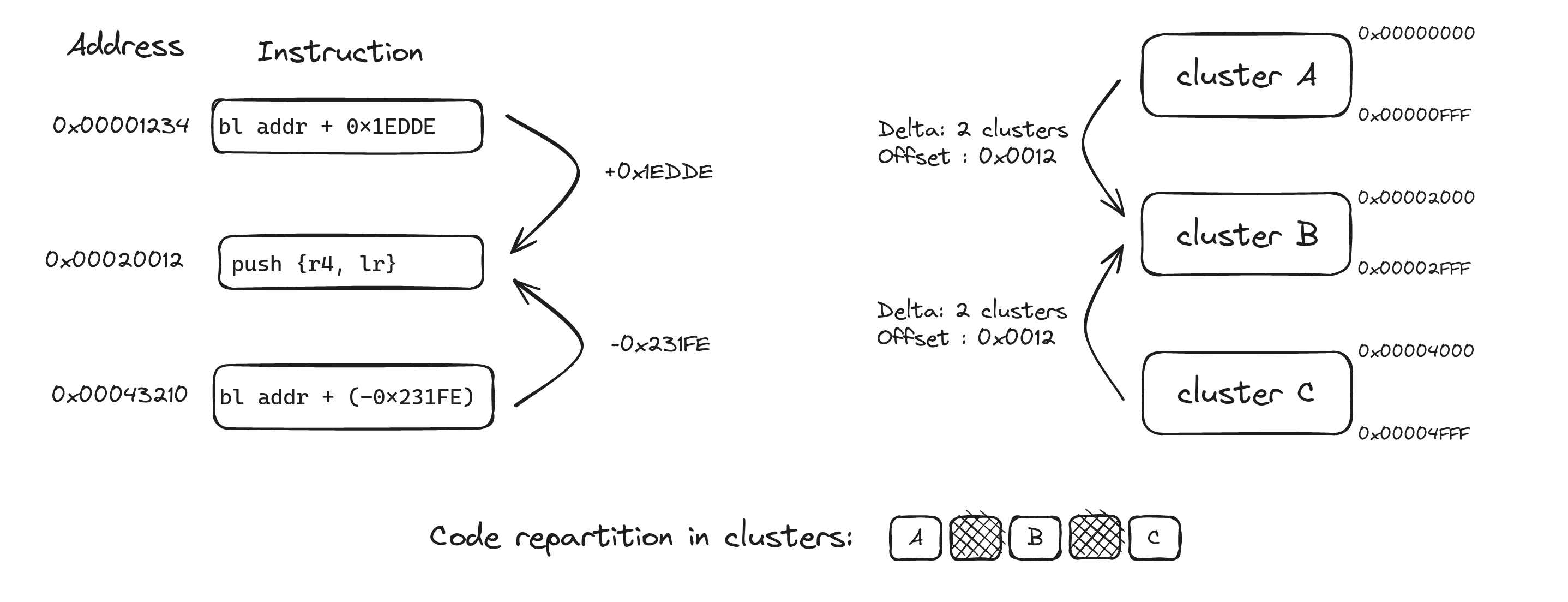
To resolve the problem of relation between clusters, let's focus on the bl instruction, for branch link. When executed, it stores the address of the next instruction into the link register (lr) then jumps to the destination address, which is the sum of the branch address plus PC-relative expression.
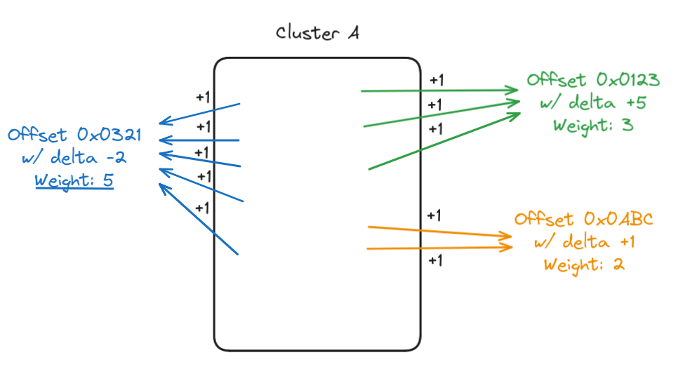
If a function is called from several parts of the firmware, the address of the bl instruction plus the PC-relative expression will point to the same address. Not knowing the correct address of the branch instruction, we can still identify the function it branches to by the offset on the destination cluster.
This approach allows us to link clusters and compute their distances. Still using Capstone-Engine, we improved our script to look for each bl instruction, check if it points outside of the cluster, and compute the distance between the current cluster and its destination. We also determine the offset in the target cluster where the bl points to.
Having a way to determine which cluster could contain part of our firmware and how distant they are, the next step is to position all of them from a reference point.
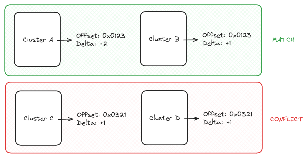
The first step is to compare all identified clusters to each other, and check if they point to the same offset with a different delta, allowing us to create a relation list.
To define our reference cluster from which we will position all others, we decided to add a weight for each call to a same function (i.e., offset) from the cluster. It's common in firmware to have a few functions with a very high number of references, like assert, log, or, for example, a low-level hardware function for embedded systems. We consider such functions as the most reliable way to properly position our clusters.
The last step before starting the positioning is to define a base position, as the relation from our reference cluster to others could be both positive (i.e. set after) and negative. We look for the number of non-zero clusters present in our dump (~ 500) and set our start position at approximately 2/3 (300).
Having defined a start position and our reference cluster (the one with the higher offset weight), we set it at the start position and look in our relation list for all related clusters to place them accordingly. Once done, we remove our reference cluster from the relation list.
After this first pass, we need to find a new cluster of reference to continue our positioning. Still using the weight system we set based on offset calls, we target the cluster already present in our current positioning with the higher weight, then add to our reconstruction not already present clusters based on the relation list. Once done, we once again erase the new reference cluster from the relation list and we continue until we are no longer able to position the remaining identified clusters.
This gave us the following result:
$./fat_explorer.py --decompile-all --compute-branch
MSWIN4.1 - sector: 512 bytes - cluster: 8 sectors
Start address: 0x0000f800
FAT0: 0x0000fa00 [158 sectors]
FAT1: 0x00023600 [158 sectors]
Root: 0x00037200 [16384 bytes]
Data: 0x0003b200

Decompiling cluster:
--------------------
100%|.........| 960/960 [00:46<00:00, 20.07it/s]

positioning cluster from branches:
----------------------------------
* positioning clusters /
>  20,21,22,23,24,25,26,27,28,29,30,31,32,33,34,35,36,37,38,39,40,41,42,43,44,45,355,47,48,49,50,51,710,53,54,55,306,307,308,309,310,311,312,313,314,315,316,-1,318,-1,320,321,322,323,324,325,326,327,328,329,330,331,332,333,492,335,336,337,338,339,340,341,493,343,344,345,346,347,348,349,350,351,352,353,354,-1,62,357,358,-1,-1,-1,-1,60,179,-1,366,367,368,369,-1,371,358,373,374,361,362,377,378,365,208,142,393,397,401,71,407,411,412,413,414,415,416,417,418,419,420,421,422,423,424,425,426,427,428,-1,382,-1,375,433,434,-1,436,437,438,439,440,441[...]
As not all clusters contain a bl instruction, some were missed, explaining the -1, but were easily replaced by the value in between two correct clusters. Moreover, we got some false positives, like 358,-1,-1,-1,-1,60,179,-1,366, where clusters 60 and 179 were not correctly positioned. Luckily for us, clusters were scattered in an ascending order, allowing us to quickly resolve such issues.
We could have added an improved validation to check once a target cluster is found if the instruction at the destination offset is a valid function prologue. However, this approach has some limitations as not all bl point to a push instruction. Having already exploitable results, we decided to not implement such feature.
Exporting found clusters in a new binary allowed us to recover almost all the firmware. Loading this result into Ghidra gave us this time a valid disassembly, allowing us to locate cryptographic-related and Bluetooth handling functions, find hardcoded keys and... you can imagine the rest.
Acknowledgments
Thanks to the Quarkslab team for reviewing this blogpost.
